
PD charging circuit capable of automatically compensating line loss and charging method

An automatic compensation and charging circuit technology, applied in battery circuit devices, circuit devices, current collectors, etc., can solve the problems of high voltage danger, small TYPEC line loss voltage, etc., to achieve line loss compensation, reduce changes, and achieve simple Effect

Pending Publication Date: 2021-11-09
深圳市世纪创新显示电子有限公司
View PDF0 Cites 1 Cited by
  • Summary
  • Abstract
  • Description
  • Claims
  • Application Information

AI Technical Summary

Problems solved by technology

One disadvantage of this solution is that when the terminal is light-loaded (small current 0A / 0.1A / 0.2A...), the actual voltage obtained by the terminal is also relatively high, 5.3V (not 5.0V): because in the case of low current, TYPE The line loss voltage caused by the C line is also small
This "high voltage" may be a high-voltage danger for some terminal equipment that requires very precise voltage

Method used


Image

  • PD charging circuit capable of automatically compensating line loss and charging method
  • PD charging circuit capable of automatically compensating line loss and charging method
  • PD charging circuit capable of automatically compensating line loss and charging method

Examples


Embodiment Construction

[0033] In order to make the purpose, technical solutions and advantages of the embodiments of the present invention clearer, a clear and complete description will be made below in conjunction with the technical solutions in the embodiments of the present invention. Obviously, the described embodiments are part of the embodiments of the present invention, and Not all examples. Based on the embodiments of the present invention, all other embodiments obtained by persons of ordinary skill in the art without making creative efforts belong to the protection scope of the present invention.

[0034] It should be noted that if there is a directional indication (such as up, down, left, right, front, back...) in the embodiment of the present invention, the directional indication is only used to explain the position in a certain posture (as shown in the accompanying drawing). If the specific posture changes, the directional indication will also change accordingly.

[0035]In addition, if...


PUM


Abstract

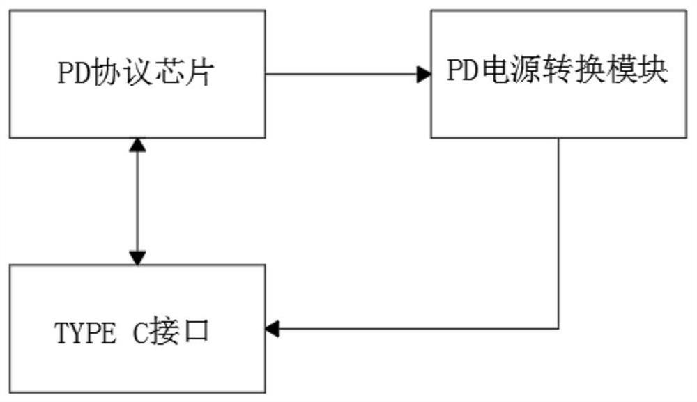
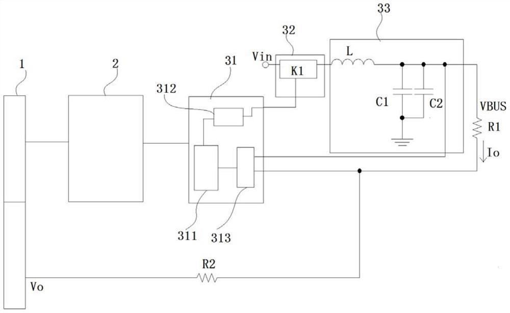
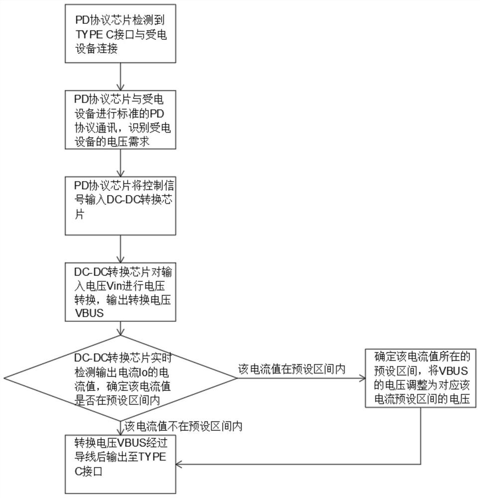
The invention relates to a PD charging circuit capable of automatically compensating line loss and a charging method. The PD charging circuit comprises a Type C interface, a PD protocol chip and a PD power supply conversion module, wherein an input voltage Vin is input into the PD power supply conversion module, the PD power supply conversion module carries out voltage conversion on the input voltage Vin, a conversion voltage VBUS is output after filtering, a voltage obtained after the conversion voltage VBUS passes through a conducting wire is a post-wire output voltage Vo, the post-wire output voltage Vo is provided for power receiving equipment, a voltage drop is generated between the conversion voltage VBUS and the post-wiore output voltage Vo due to the parasitic resistance R2 of the conducting wire, a DC-DC conversion chip detects the current of the power receiving equipmentin real time through a current detection amplification unit to obtain a preset interval where the current value is located, the voltage of the conversion voltage VBUS is adjusted to a voltage corresponding to the preset interval of the current so as to make the post-wire output voltage Vo reach a set value, and the post-wire output voltage Vo is output to the TYPE C interface through the conducting wire.

Description

technical field [0001] The present invention relates to the technical field of DC charging, and more specifically, to a PD charging circuit and charging method for automatically compensating for line loss. Background technique [0002] Due to its powerful electrical performance specifications and ease of use, TYPE C has increasingly become a standard interface for various electronic products, such as monitors, mobile phones, tablets, notebook computers and power adapters, and the PD charging function is the performance of TYPE C. The core parameters in the specification. [0003] Due to the large external charging current of the PD (the standard upper limit is 100W), the line loss voltage is also large after the large current is transmitted through the Type C line, especially when the Type C line is long. As a result, the voltage to the terminal is low, even lower than the minimum voltage specification of the terminal. So how to increase the actual voltage obtained by the ...

Claims


Application Information

Patent Timeline
Patent Type & Authority Applications(China)
IPC IPC(8): H02J7/00
Inventor 孔意强黎旭沈峻
Owner 深圳市世纪创新显示电子有限公司
Learn More