Battery
A battery and electrode body technology, applied in secondary batteries, circuits, secondary battery manufacturing, etc., to achieve good impregnation and improve drop resistance
Pending Publication Date: 2021-11-09
MURATA MFG CO LTD
View PDF3 Cites 0 Cited by
- Summary
- Abstract
- Description
- Claims
- Application Information
AI Technical Summary
Problems solved by technology
In addition, Patent Document 2 does not have the electrolyte holding function of the electrode body itself as in the present invention.
In addition, Patent Document 3 is a technique for suppressing an internal short circuit, which is different from the present invention in which a diaphragm is compressed to improve longitudinal vibration.
Method used
View moreImage
Smart ImageViewing Examples
Examples
Embodiment 1
[0116] Example 1: 0.08, Example 2: 0.14, Example 3: 0.17
Login to View More PUM
| Property | Measurement | Unit |
|---|---|---|
| Width | aaaaa | aaaaa |
| Width | aaaaa | aaaaa |
Abstract
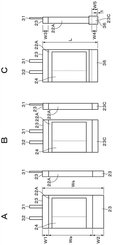
Provided is a battery in which a case accommodates: a coil structure electrode body comprising a band-shaped positive electrode comprising a positive electrode lead, a band-shaped negative electrode comprising a negative electrode lead, and a band-shaped separator which is disposed between the positive electrode and the negative electrode; and an electrolyte. The positive electrode lead and the negative electrode lead are drawn out from one end surface of the electrode body, and the electrode body comprises a separator molding part which protrudes from the other end surface thereof. The battery satisfies Formula 1 and Formula 2. Formula 1: 0.08<=W2 / Ws<=0.17 Formula 2: 0.20<=W4 / W2<=0.53 In Formula 1 and Formula 2: W1 is the quantity by which the separator on the one end surface side extends beyond the negative electrode; W2 is the quantity by which the separator on the other end surface side extends beyond the negative electrode; Ws is the width of the separator; and W4 is a dimension from an end part of the negative electrode to a bottom part of the electrode body (excluding a tape thickness).
Description
technical field [0001] The present invention relates to a battery having an electrode body in which a positive electrode and a negative electrode are laminated with a separator interposed therebetween. Background technique [0002] In recent years, a large number of portable electronic devices such as smartphones and notebook computers have appeared, and efforts have been made to reduce their size and weight. As portable power sources for these electronic devices, non-aqueous electrolyte secondary batteries (such as lithium ion secondary batteries) are used. As an example of a secondary battery, a structure having an electrode body in which a positive electrode and a negative electrode are stacked with a separator interposed therebetween is known. [0003] For example, Patent Document 1 describes that, while achieving a large discharge capacity, by redesigning the conventional electrode dimensions (the relationship between the positive electrode and the negative electrode),...
Claims
Login to View More Application Information
Patent Timeline
 IPC IPC(8): H01M10/04H01M10/0587H01M50/119H01M50/528H01M50/531H01M50/572H01M50/103H01M50/534H01M50/586H01M50/595
CPCH01M10/0587Y02E60/10H01M50/528Y02P70/50H01M10/0525H01M50/119H01M50/103H01M50/533H01M50/534H01M50/595H01M50/586H01M10/0413H01M10/0564
Inventor 堀越吉一西家大贵德川秀昭大塚正博秋月直人
Owner MURATA MFG CO LTD
Features
- R&D
- Intellectual Property
- Life Sciences
- Materials
- Tech Scout
- Unparalleled Data Quality
- Higher Quality Content
- 60% Fewer Hallucinations
Learn More Browse by: Latest US Patents, China's latest patents, Technical Efficacy Thesaurus, Application Domain, Technology Topic, Popular Technical Reports.
© 2025 PatSnap. All rights reserved.Legal|Privacy policy|Modern Slavery Act Transparency Statement|Sitemap|About US| Contact US: help@patsnap.com


