Laser cutting device for cutting small nameplates

A laser cutting and nameplate technology, applied in laser welding equipment, other manufacturing equipment/tools, welding equipment, etc., can solve the problems of low positioning accuracy and abnormal cutting, so as to increase positioning accuracy, avoid defective products, and avoid inaccuracy sexual effect

Active Publication Date: 2021-11-12
启东市神龙工业配套有限公司
View PDF10 Cites 3 Cited by
  • Summary
  • Abstract
  • Description
  • Claims
  • Application Information

AI Technical Summary

Problems solved by technology

[0005] The object of the present invention is to provide a laser cutting device for cutting small nameplates in view of the deficiencies of the prior art. The attitude of the nameplate is adjusted through the adjustment component, and then the nameplate is effectively positioned through the positioning component, so that the nameplate The position of the nameplate is determined, and the nameplate is adsorbed and cut through the adsorption component, so that the position of the nameplate is determined, which increases the positioning accuracy. At the same time, the circular movement also improves the work efficiency and avoids the problem of abnormal cutting caused by low positioning accuracy.

Method used


Image

  • Laser cutting device for cutting small nameplates
  • Laser cutting device for cutting small nameplates
  • Laser cutting device for cutting small nameplates

Examples


Embodiment 1

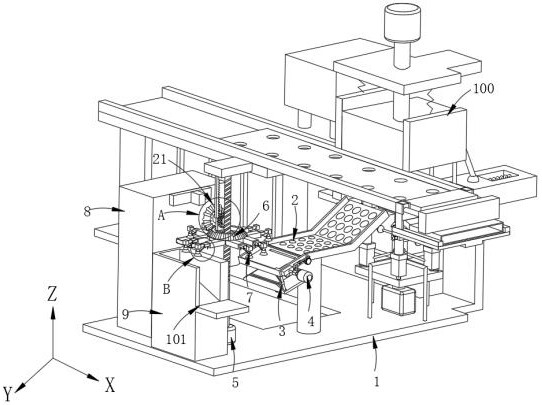
[0098] Such as figure 1 As shown, a laser cutting device for cutting small nameplates, including:

[0099] Main board 1,

[0100] stamping system 101, the stamping system 101 is connected with the main panel 1; and

[0101] A laser cutting system 102, the laser cutting system 102 is located at the discharge end of the stamping system 101;

[0102] The output end of the stamping system 101 is connected with a ball slideway 2, and its surface is rotated with several rolling elements; the positioning frame 35 is rotated and set at the discharge end of the ball slideway 2;

[0103] When the stamping device of the nameplate plate on the main plate 1 is stamped, it will fall on the ball slideway 2 at this time. Since the ball slideway 2 is equipped with rolling balls, the nameplate plate will move along the rolling balls under the action of gravity. Slide into the positioning frame 35;

[0104] Laser cutting system 102 includes:

[0105] Adjustment component 3, the adjustment c...

Embodiment 2

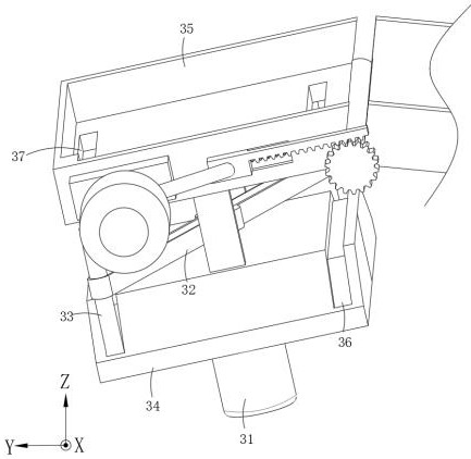
[0128] Such as Figure 5-13 As shown, the components that are the same as or corresponding to those in the first embodiment are marked with the corresponding reference numerals in the first embodiment. For the sake of simplicity, only the differences from the first embodiment will be described below. The difference between this embodiment two and embodiment one is:

[0129] Such as Figure 5 As shown, preferably, the transmission assembly 21 includes:

[0130] a drive assembly 5, the drive assembly 5 is connected to the main board 1; and

[0131] The steering assembly 6, the steering assembly 6 switches the nameplate captured by the adsorption assembly 7 to different stations;

[0132] Such as Figure 5 As shown, preferably, the drive assembly 5 includes:

[0133] A driving motor 51, which is arranged above the main board 1;

[0134] Drive screw mandrel 52, it is arranged on the output end of drive motor 51;

[0135] A driving wire block 53, the inside of which engages ...

Embodiment 3

[0159] Such as Figure 14-19 As shown, the parts that are the same as or corresponding to those in the first embodiment are marked with the corresponding reference numerals in the first embodiment. For the sake of simplicity, only the differences from the first embodiment are described below. The difference between this embodiment two and embodiment one is:

[0160] Such as Figure 14 As shown, preferably, the stamping system 101 includes:

[0161] Rack 1001;

[0162] Also includes:

[0163] stamping assembly 1002, which is connected to the frame 1001;

[0164] The second positioning component 1003 is arranged inside the frame 1001;

[0165] Grinding assembly 1004, which is arranged on the top of the second positioning assembly 1003;

[0166]When the nameplate is stamped and moves downward, the second positioning assembly 1003 provides a driving force to drive the grinding assembly 1004 to expand upward, thereby completing the positioning of the nameplate, and the namepl...


PUM


Abstract

The invention provides a laser cutting device for cutting small nameplates. The laser cutting device comprises a main body plate, further comprises a ball slide way arranged above the main body plate and provided with balls rotatably arranged on the surface, further comprises an adjusting assembly rotatably connected to the tail end of the left side of the ball slide way, and further comprises a positioning assembly arranged on the side face of a channel of the adjusting assembly. After a nameplate is stamped on a stamping device on the main body plate, the nameplate can fall on the ball slide way and slide into a positioning frame, and due to the fact that the position of the nameplate in the horizontal and vertical state is uncertain, an adjusting driving part starts to move to drive a set of extrusion slide rods to extrude the diagonal ends of a workpiece through a through groove formed in the positioning frame, at the moment, the workpiece rotates by 90 degrees to enable the long edge to be attached to the lower left end of the positioning frame, and the rotation amplitude stops when the extrusion sliding rods move to the tail end of a trapezoidal groove in a trapezoidal sliding table, so that the falling nameplate always keeps a posture, and the positioning accuracy is improved.

Description

technical field [0001] The invention relates to the field of nameplate manufacturing, in particular to a laser cutting device for cutting small nameplates. Background technique [0002] In today's industrial technology development, laser technology has become an industry trend. Compared with traditional cutting machines, laser technology has great advantages in cutting. The working efficiency of laser cutting is far greater than that of traditional cutting. At the same time, the section of the cut workpiece is relatively flat, which greatly increases the aesthetics of the workpiece after cutting. [0003] Chinese patent CN106624357B discloses a plate positioning device in a laser cutting line, including a base, a cyclic positioning mechanism, a plate insertion mechanism and a control mechanism. On the side of the circular positioning mechanism, the control mechanism is electrically connected with the circular positioning mechanism and the inserting plate mechanism; the circ...

Claims


Application Information

Patent Timeline
IPC IPC(8): B23P23/06B23K26/38B23K26/70
CPCB23P23/06B23K26/38B23K26/702
Inventor 施恺
Owner 启东市神龙工业配套有限公司
Why Eureka
Try Eureka