Supercharge Your Innovation With Domain-Expert AI Agents!

Surface treatment equipment for stationary blade of steam turbine and treatment method of surface treatment equipment

A technology for surface treatment and stationary blades, which is applied to the surface treatment equipment and the treatment field of the stationary blades of steam turbines, can solve the problems of reducing the practicability of the device, increasing the workload of the staff, affecting the quality of burr removal, etc., so as to improve the practicability and improve the The effect of convenience

Active Publication Date: 2021-11-12
南通兴东叶片科技有限公司
View PDF4 Cites 1 Cited by
  • Summary
  • Abstract
  • Description
  • Claims
  • Application Information

AI Technical Summary

Problems solved by technology

[0003] In the prior art, when designing and manufacturing the surface treatment equipment for the steam turbine stator blades, most designers will pay attention to the processing strength of the design device, so that the burrs on the surface of the workpiece can be completely removed when processing the stator blade workpieces, but when processing the burrs During operation, most of the operations are still manually removed, which not only affects the quality of burr removal, but also increases the workload of the staff, thereby reducing the practicability of the device

Method used


Image

  • Surface treatment equipment for stationary blade of steam turbine and treatment method of surface treatment equipment
  • Surface treatment equipment for stationary blade of steam turbine and treatment method of surface treatment equipment
  • Surface treatment equipment for stationary blade of steam turbine and treatment method of surface treatment equipment

Examples


Embodiment Construction

[0019] The following will clearly and completely describe the technical solutions in the embodiments of the present invention with reference to the accompanying drawings in the embodiments of the present invention. Obviously, the described embodiments are only some, not all, embodiments of the present invention. Based on the embodiments of the present invention, all other embodiments obtained by persons of ordinary skill in the art without making creative efforts belong to the protection scope of the present invention.

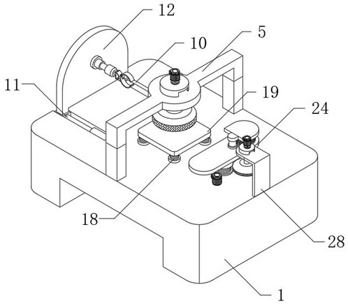
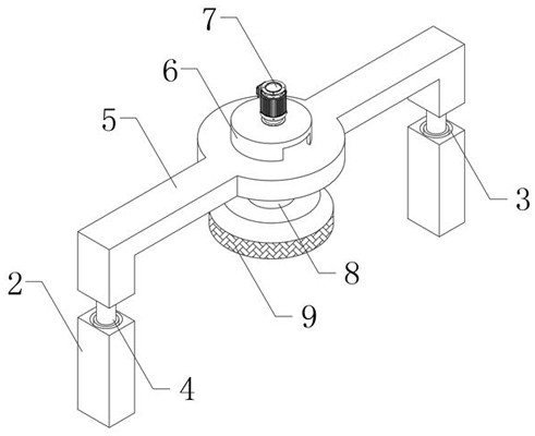
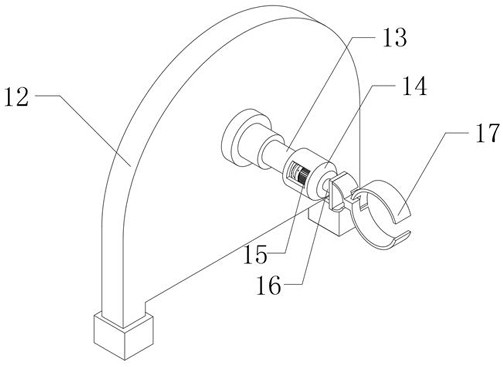
[0020] The present invention provides such Figure 1-5 The shown surface treatment equipment and treatment method of a steam turbine stator blade includes a workbench 1, one side of the inner walls of two chutes 10 is fitted with a support plate 12, and the outer walls at both ends of the bottom of the support plate 12 are respectively connected to the The inner walls of the two chutes 10 are slidingly connected, one side of the support plate 12 is fixed with ...


PUM


Abstract

The invention discloses surface treatment equipment for a stationary blade of a steam turbine and a treatment method of the surface treatment equipment. The surface treatment equipment comprises a workbench, wherein supporting columns are fixedly arranged in the middle positions of the two sides of the top end of the workbench; clamping grooves are formed in the middle positions of the top ends of the two supporting columns; first electric telescopic rods are arranged on the inner walls of the two clamping grooves in a clamped mode; first supporting frames are fixedly arranged at the output ends of the two first electric telescopic rods correspondingly; and first rotating shafts are arranged in the middles of the bottoms of the first supporting frames in a penetrating and inserting mode. According to the surface treatment equipment for the stationary blade of the steam turbine and the treatment method of the surface treatment equipment, the two first electric telescopic rods are started, so that the first supporting frames with grinding pieces move up and down to grind the surface of the workpiece of the stationary blade of the steam turbine at the upper end of a grinding table, and the angle and direction of the workpiece are adjusted in cooperation with a mechanical arm, so that the grinding structure can comprehensively grind the surface of the workpiece, burrs of the workpiece are removed more thoroughly, and therefore the practicability of the device is improved.

Description

technical field [0001] The invention relates to the technical field of surface treatment equipment, in particular to a surface treatment equipment and a treatment method for steam turbine stator blades. Background technique [0002] The traditional steam turbine stator blade processing equipment is mainly used for grinding and polishing the burr area on the surface of the stator blade workpiece and grinding and other operations. With the development of modern technology, the direction of use of steam turbines continues to increase, so The production requirements of the workpiece at the upper end will also be stricter, especially the stator blade at the upper end, which acts on the main output area of ​​the steam turbine. An essential device in the production of stationary blades; [0003] In the prior art, when designing and manufacturing the surface treatment equipment for the steam turbine stator blades, most designers will pay attention to the processing strength of the ...

Claims


Application Information

Patent Timeline
Patent Type & Authority Applications(China)
IPC IPC(8): B24B1/00B24B9/00B24B19/14B24B41/06B24B47/12B24B41/02B24B55/06B24B41/04B24B41/00B08B1/04B08B13/00
CPCB24B1/00B24B9/00B24B19/14B24B41/06B24B47/12B24B41/02B24B55/06B24B41/04B24B41/005B08B13/00B08B1/32
Inventor 张勇军吴健
Owner 南通兴东叶片科技有限公司
Features
  • R&D
  • Intellectual Property
  • Life Sciences
  • Materials
  • Tech Scout
  • Unparalleled Data Quality
  • Higher Quality Content
  • 60% Fewer Hallucinations
Learn More