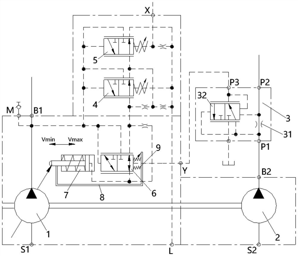
Load-sensitive pump system, hydraulic control system and engineering machinery

A technology of load-sensing pumps and construction machinery, which is applied in the fields of load-sensing pump systems, hydraulic control systems and construction machinery, and can solve the problems of non-energy saving, hydraulic system output power reduction, etc., and achieve the effect of high implementability

Pending Publication Date: 2021-11-12
XUZHOU HEAVY MASCH CO LTD
View PDF0 Cites 0 Cited by
  • Summary
  • Abstract
  • Description
  • Claims
  • Application Information

AI Technical Summary

Problems solved by technology

[0004] From the hydraulic pump input torque formula T=P*V / 2π, it can be seen that the greater the load pressure P, the pump displacement has a maximum limit Vmax, otherwise the torque T will exceed the current output torque of the engine, which will cause the engine to stall For this reason, when the load sensing pump is selected for crane products, it usually has a constant power control function (LA), which depends on the input torque of the power unit at the lowest speed. After the setting value is fixed, even if the engine speed increases, the When the provided torque increases, the displacement of the pump will still decrease after the outlet pressure of the pump reaches a certain value, which will eventually reduce the output power of the hydraulic system and the power utilization rate of the engine. In comparison, the system consumes a lot of energy and is not energy-saving.

Method used


Image

  • Load-sensitive pump system, hydraulic control system and engineering machinery

Examples


Embodiment Construction

[0028] Various exemplary embodiments of the present disclosure will now be described in detail with reference to the accompanying drawings. The description of the exemplary embodiments is illustrative only, and in no way restricts the disclosure, its application or uses. The present disclosure can be implemented in many different forms and is not limited to the examples herein. Rather, these embodiments are provided so that this disclosure will be thorough and complete, and will fully convey the scope of the disclosure to those skilled in the art. It should be noted that relative arrangements of parts and steps, compositions of materials, numerical expressions and numerical values ​​set forth in these embodiments should be interpreted as illustrative only and not as limiting, unless specifically stated otherwise.

[0029] "First", "second" and similar words used in the present disclosure do not indicate any order, quantity or importance, but are only used to distinguish diffe...


PUM


Abstract

The invention relates to a load-sensitive pump system, a hydraulic control system and engineering machinery. The load-sensitive pump system comprises a variable pump, a metering pump, a variable control mechanism, a control oil path and a pressure tapping valve; the metering pump and the variable pump are driven by the same driving mechanism; the variable control mechanism is used for controlling the variable pump; and the pressure tapping valve is configured to enable part of output pressure of the metering pump to act on the control end of the variable control mechanism through the control oil path, so that the maximum displacement of the variable pump is increased when the driving rotating speed of the driving mechanism is increased. The pressure tapping valve is arranged, and the pressure tapping valve introduces part of pressure change signals of the metering pump into the control end of the variable control mechanism, so that when the driving rotating speed of the driving mechanism is increased, the variable control mechanism can increase the maximum displacement of the variable pump. According to the load-sensitive pump system, an electric controller or a wire harness does not need to be additionally arranged, through the hydraulic control oil path, the effect that the power is controlled in a variable mode along with the rotating speed is achieved, and high feasibility is achieved.

Description

technical field [0001] The present disclosure relates to the technical field of construction machinery, in particular to a load sensitive pump system, a hydraulic control system and construction machinery. Background technique [0002] The power unit of the crane mostly uses the engine to drive the hydraulic pump group to provide power for the crane's on-board operation system (winch, luffing, telescopic and slewing, etc.). Reduced, the maximum torque point is often in the middle speed range, and the output torque is very low at low speeds, for example, at 800rpm, the output torque is 800Nm, and it reaches 1600Nm at 1400rpm. [0003] A load-sensing pump system is commonly used in the crane hydraulic system. The hydraulic control handle is used to control the load-sensing multi-way valve. The valve has a load-sensing oil circuit connected to a load-sensing pump. By controlling the opening of the multi-way valve, To achieve the effect of system speed regulation, in addition, ...

Claims


Application Information

Patent Timeline
Patent Type & Authority Applications(China)
IPC IPC(8): F15B11/17F15B13/06B66C13/20
CPCF15B11/17F15B11/161F15B13/06B66C13/20F15B2211/20538F15B2211/20546F15B2211/20576F15B2211/255
Inventor 向小强刘东宏仝猛王建成陈龙
Owner XUZHOU HEAVY MASCH CO LTD
Why Eureka
Try Eureka