Hydraulic pry of hydraulic injection pump

A technology for injecting pumps and hydraulic pressure, which is applied in fluid pressure actuating devices, fluid pressure actuating system components, pumps, etc. It can solve the problems of small displacement and difficulty in meeting the requirements of oil fields, and achieve the effect of strengthening the bearing capacity

Active Publication Date: 2020-12-04
DEZHOU UNITED GASOLINEEUM MACHINERY
View PDF6 Cites 1 Cited by
  • Summary
  • Abstract
  • Description
  • Claims
  • Application Information

AI Technical Summary

Problems solved by technology

However, the existing hydraulic injection equipment has a small displacement, which is difficult to meet the requirements of injection operations such as oilfield profile control, pressure displacement, and fracturing.

Method used


Image

  • Hydraulic pry of hydraulic injection pump
  • Hydraulic pry of hydraulic injection pump
  • Hydraulic pry of hydraulic injection pump

Examples


Embodiment 1

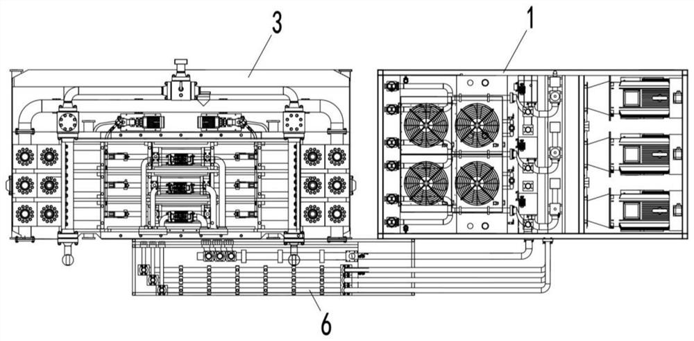
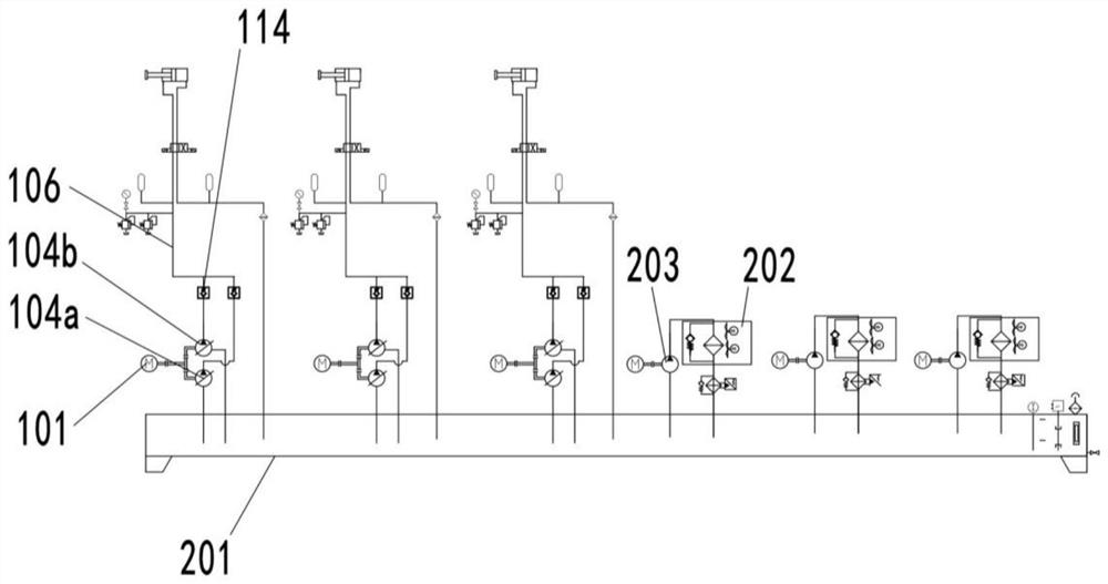
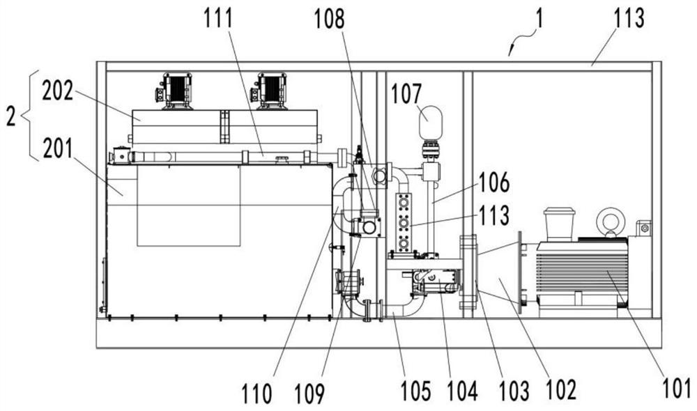
[0066] Such as Figure 1 to Figure 4 As shown, a hydraulic pump station skid 1 includes a plurality of oil supply units, each oil supply unit includes a power element 101, a transfer case 103 and two hydraulic oil pumps 104a, 104b, the power element 101 and the transfer case 103 The input end is connected by transmission, and the transfer case 103 has two output ends, and the output ends of the transfer case 103 are respectively connected by transmission to the hydraulic oil pumps 104a and 104b.

[0067] In the prior art, the displacement of the hydraulic oil pumps 104a and 104b cannot be selected arbitrarily, especially when selecting a hydraulic oil pump with a large displacement, it is often limited by factors such as technical maturity and price. The hydraulic pump station of this embodiment In the skid 1, one power element 101 is used to drive two hydraulic oil pumps 104a, 104b, and the transmission is carried out through the transfer case 103. In the case of using a smal...

Embodiment 2

[0083] Such as Figure 1 to Figure 9 As shown, a hydraulic oil tank, the hydraulic oil tank 2 includes a box body 201, a radiator 202 and a radiator oil pump 203, the suction end of the radiator oil pump 203 is connected to the box body 201, the discharge end of the radiator oil pump 203 is connected to the radiator 202, and the heat dissipation The discharge end of the device 202 is connected with the box body 201. In the traditional hydraulic profile control pump, the radiator 202 is connected to the oil return pipeline 111, while the hydraulic oil tank 2 in this embodiment adopts bypass heat dissipation. On the one hand, the radiator 202 is protected from the impact of the returning hydraulic oil. , it is convenient to match a reasonable heat dissipation oil pump 203 according to heat dissipation requirements, so as to efficiently dissipate heat from hydraulic oil.

[0084]There are multiple radiators 202 and cooling oil pumps 203 , and the radiators 202 correspond to the ...

Embodiment 3

[0096] Such as Figure 10 to Figure 13 As shown, a hydraulic injection pump hydraulic skid 3 includes a frame 301 and three working units connected to the frame 301 . The working unit includes a hydraulic cylinder 302 and a first hydraulic end and a second hydraulic end symmetrically arranged on both sides of the hydraulic cylinder 302 . The hydraulic cylinder 302 includes a hydraulic piston rod 303, the hydraulic piston rod 303 has a first output end and a second output end oppositely arranged, the first output end is connected to the first hydraulic end, and the second output end is connected to the second hydraulic end .

[0097] The frame 301 is installed on the upper side of the base 10, and the base 10 is used to provide support for the frame 301, the slurry suction pipeline system 7, the slurry discharge pipeline system 8 and the spraying system 9.

[0098] In this embodiment, there are three working units, but it should be noted that there may be 2 to 10 working unit...


PUM


Abstract

The invention provides a hydraulic pry of a hydraulic injection pump, and relates to the technical field of petroleum equipment. The hydraulic pry comprises a machine frame and a plurality of workingunits connected with the machine frame, each working unit comprises a hydraulic cylinder, a first hydraulic end and a second hydraulic end, and each first hydraulic end and the corresponding second hydraulic end are symmetrically arranged on the two sides of each hydraulic cylinder, and each hydraulic cylinder comprises a hydraulic piston rod; and each hydraulic piston rod is provided with a firstoutput end and a second output end which are oppositely arranged, each first output end is connected with the corresponding first hydraulic end, and each second output end is connected with the corresponding second hydraulic end. According to the hydraulic pry of the hydraulic injection pump, the maximum displacement of the hydraulic injection pump is increased by increasing the number of the working units.

Description

technical field [0001] The invention relates to the technical field of petroleum equipment, in particular to a hydraulic injection pump hydraulic skid. Background technique [0002] In the crankshaft plunger pump of the prior art, the stroke is short, the number of reversing times is large, the plunger moves frequently, and the life of the wearing parts is short. For example, the service life of the valve seat, valve and valve rubber at the fluid end is only a few In addition, the output pressure and flow coverage of this crankshaft plunger pump is relatively narrow. To improve the coverage, it is necessary to replace the liquid end with a different cylinder diameter; in addition, when the plunger changes direction frequently and quickly, the pressure The fracturing fluid is discharged before it is fully inhaled, resulting in low suction efficiency and low work efficiency; in addition, the fracturing pump is integrated with a crankshaft, power input gear, connecting rod, flu...

Claims


Application Information

Patent Timeline
Patent Type & Authority Applications(China)
IPC IPC(8): F04B9/113F04B17/03F04B23/02F04B23/04F04B23/06F04B49/00F04B49/06F04B53/08F04B53/10F04B53/14F04B53/16F04B53/20
CPCF04B9/113F04B17/03F04B23/02F04B23/04F04B23/06F04B49/002F04B49/065F04B53/08F04B53/10F04B53/14F04B53/166F04B53/20F15B13/06F15B13/0846F15B13/086F15B21/02F15B21/08F15B2211/20515F15B2211/6336
Inventor 王佳琦张浩谦程贵华王继平石宛铭宫兆玲王宗雷杨成永张桂昌李曼曼
Owner DEZHOU UNITED GASOLINEEUM MACHINERY
Why Eureka
Try Eureka