
Circulating fluidized bed boiler

A circulating fluidized bed and boiler technology, which is applied in the direction of fluidized bed combustion equipment, burning fuel in a molten state, and the transportation of non-flammable liquid/gas, can solve the problems of increasing fuel consumption, heat loss of circulating fluidized bed boilers, Affect secondary air and other issues to achieve the effect of improving thermal efficiency, overcoming the high carbon content of fly ash, and improving utilization

Pending Publication Date: 2021-11-12
蒋俊芳
View PDF0 Cites 0 Cited by
  • Summary
  • Abstract
  • Description
  • Claims
  • Application Information

AI Technical Summary

Problems solved by technology

As the concentration of materials in the furnace increases, the back pressure in the furnace is relatively high, which affects the effective blowing of the secondary air into the center of the furnace for oxygen supplementation, resulting in the fly ash being brought out before being completely burned. the furnace, resulting in the heat loss of the circulating fluidized bed boiler
Fly ash accounts for about 70% of the bottom slag and fly ash after combustion in circulating fluidized bed boilers. Excessively high carbon content in fly ash increases fuel consumption for power plants

Method used


Image

  • Circulating fluidized bed boiler
  • Circulating fluidized bed boiler
  • Circulating fluidized bed boiler

Examples


Embodiment Construction

[0031] In order to make the purpose, technical solutions and advantages of the embodiments of the present invention clearer, the technical solutions in the embodiments of the present invention will be clearly and completely described below in conjunction with the drawings in the embodiments of the present invention. Obviously, the described embodiments It is a part of embodiments of the present invention, but not all embodiments. The components of the embodiments of the invention generally described and illustrated in the figures herein may be arranged and designed in a variety of different configurations.

[0032] Accordingly, the following detailed description of the embodiments of the invention provided in the accompanying drawings is not intended to limit the scope of the claimed invention, but merely represents selected embodiments of the invention. Based on the embodiments of the present invention, all other embodiments obtained by persons of ordinary skill in the art wi...


PUM


Abstract

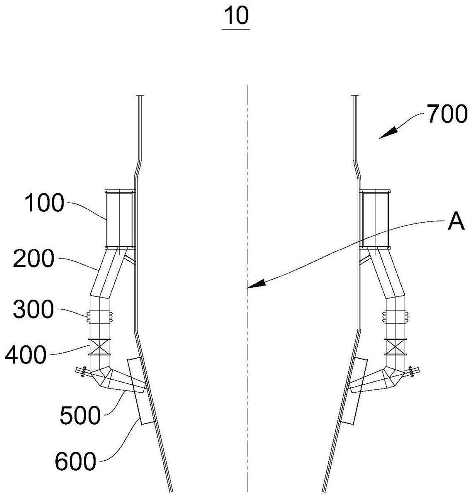
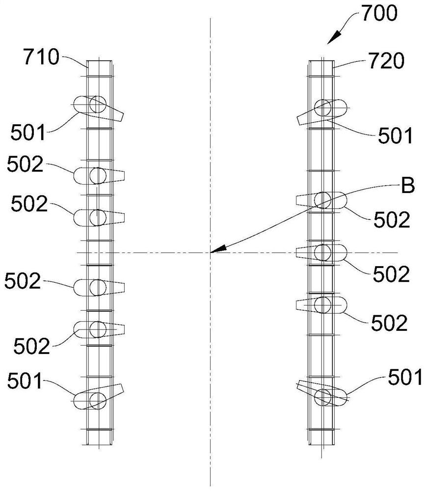
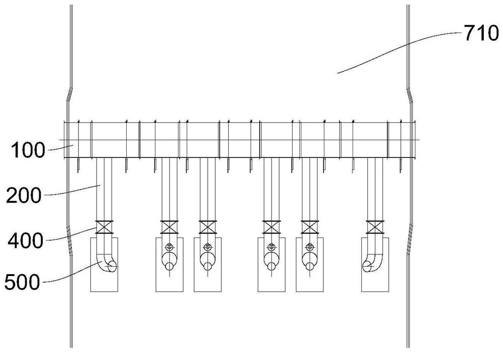
The embodiment of the invention provides a circulating fluidized bed boiler, and relates to the field of combustion parts of circulating fluidized bed boilers. The combustion efficiency of the boiler is improved. The circulating fluidized bed boiler comprises a boiler body and a secondary air nozzle; the secondary air nozzle is a conical pipe, the secondary air nozzle is provided with a large end and a small end which are opposite in position, the secondary air nozzle is arranged on the boiler body, and the small end of the secondary air nozzle extends into the boiler body; the secondary air nozzle comprises a first nozzle arranged at the corner of the boiler body; the center line of the first nozzle and the center line of a hearth of the boiler body form an included angle; the secondary air nozzle adopts a conical structure, so that the kinetic energy of secondary air can be increased; the first nozzle is obliquely arranged towards the center line of the hearth, abrasion of secondary air to a side wall water cooling wall tube can be prevented, meanwhile, the influence of the secondary air to wall-attached downflow can be reduced to the maximum extent, the material mixing effect is guaranteed, the boiler heat efficiency is improved, and therefore the carbon content of fly ash is reduced, the heat loss of the boiler is reduced, and the use cost is reduced.

Description

technical field [0001] The invention relates to the field of combustion components of a circulating fluidized bed boiler, in particular to a circulating fluidized bed boiler. Background technique [0002] In response to the national call for energy conservation and emission reduction, many power plants have adopted circulating fluidized bed boilers with low nitrogen combustion technology; the material concentration in circulating fluidized bed boilers with low nitrogen combustion technology is relatively high, which can meet the requirements for controlling NOx emissions. As the concentration of materials in the furnace increases, the back pressure in the furnace is relatively high, which affects the effective blowing of the secondary air into the center of the furnace for oxygen supplementation, resulting in the fly ash being brought out before being completely burned. The furnace is damaged, resulting in the heat loss of the circulating fluidized bed boiler. Fly ash accou...

Claims


Application Information

Patent Timeline
Patent Type & Authority Applications(China)
IPC IPC(8): F23C10/20F23C10/18F23L9/00
CPCF23C10/20F23C10/18F23L9/00
Inventor 蒋俊芳
Owner 蒋俊芳
Learn More