Pulverized coal spray head structure

A sprinkler and pulverized coal technology, which is applied in the directions of block/powder supply/distribution, burners for burning powder fuel, and combustion methods, etc. The problems such as the large degree of pulverized powder aggregation can be achieved to increase the consumption of pulverized coal, save coal resources and costs, and improve the utilization rate of pulverized coal.

Pending Publication Date: 2021-11-12
章丘华明水泥新型建材有限公司
View PDF0 Cites 0 Cited by
  • Summary
  • Abstract
  • Description
  • Claims
  • Application Information

AI Technical Summary

Problems solved by technology

[0003] However, although the pulverized coal sprayed from the nozzle is boosted by air, the degree of aggregation of the pulverized coal is still large, that is, the density of the pulverized coal is high, so that the adequacy of the pulverized coal in contact with the oxygen in the air needs to be improved. The combustion adequacy of pulverized coal also needs to be improved

Method used


Image

  • Pulverized coal spray head structure
  • Pulverized coal spray head structure
  • Pulverized coal spray head structure

Examples


Embodiment 1

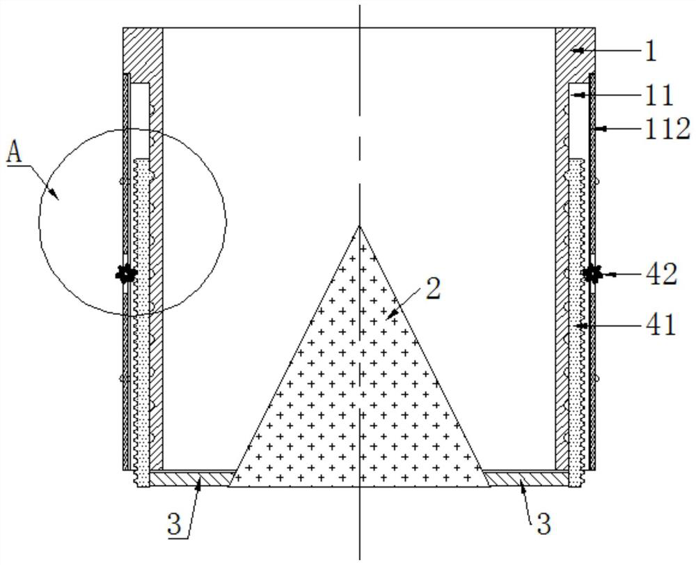
[0055] Such as Figure 2-5 As shown, a pulverized coal nozzle structure includes a nozzle 1 , a cone 2 , a support rod 3 , and a lifting mechanism 4 .

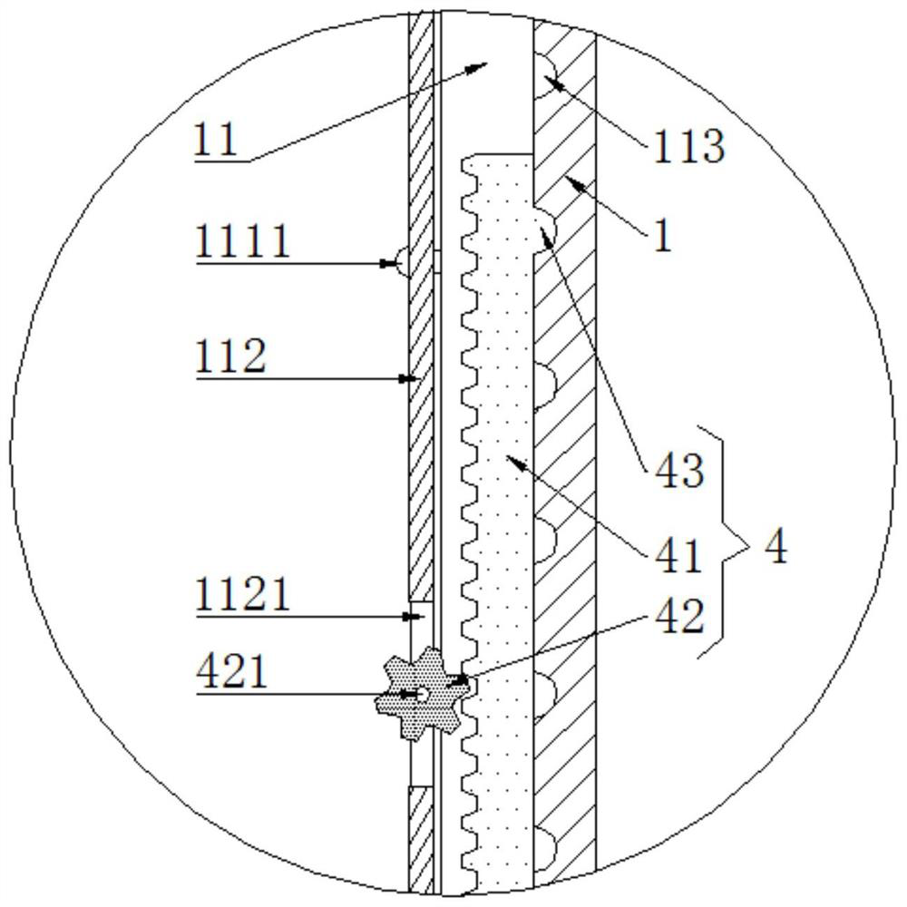
[0056] Such as figure 2 As shown, the spout 1 is provided with a conical block 2 with its tip facing upwards, and two support rods 3 are welded at the lower end of the conical block 2, and the support rods 3 are connected with the pipe wall of the spout 1 through a lifting mechanism 4.

[0057] Such as Figure 4 As shown, the setting of the cone block 2 can form an annular powder injection port between the side wall of the cone block 2 and the nozzle edge of the nozzle 1, so that the coal powder flowing through the cone block 2 is dispersed by the cone block 2, The dispersed pulverized coal is sprayed out in a ring after passing through the powder injection port, and the pulverized coal sprayed out in a ring can be more evenly dispersed, which improves the adequacy of the contact between the pulverized coal and the oxygen i...

Embodiment 2

[0071] Such as Figure 6-11 As shown, this embodiment 2 makes further improvements on the basis of embodiment 1: in the structure of a pulverized coal nozzle in this embodiment 2, the cone block 2 includes a cone riser 21, an adjusting screw 22, a first cone Side plate 23, second cone side plate 24, adjustment connecting rod 25, adjustment block 26.

[0072] Such as Figure 11 As shown, the upper end of the adjusting screw 22 is rotationally connected with the cone 21 . Concrete: the lower end of the cone riser 21 is provided with a rotating hole 211, the hole wall of the rotating hole 211 is provided with an annular groove 2111, the upper end of the adjusting screw rod 22 is welded with an annular rail 221, and the annular rail 221 can rotate with the annular groove 2111.

[0073] Such as Figure 11 As shown, when the adjustment screw 22 and the cone cap 21 need to be installed together, it is only necessary to squeeze the annular rail 221 on the adjustment screw 22 into t...


PUM


Abstract

The invention discloses a pulverized coal spray head structure, and relates to the technical field of coal injection equipment. The pulverized coal spray head structure comprises a spray pipe, a conical block, a supporting rod and a lifting mechanism, wherein the conical block with an upward tip is arranged in the spray pipe, the supporting rod is arranged at the lower end of the conical block, the supporting rod is connected to the pipe wall of the spray pipe through the lifting mechanism, when the supporting rod descends, the distance between the side wall of the conical block and the edge of the pipe opening of the spraying pipe is increased, the pulverized coal spraying amount is increased, and when the supporting rod ascends, the distance between the side wall of the conical block and the edge of the pipe opening of the spraying pipe is decreased, and the pulverized coal spraying amount is decreased. According to the pulverized coal spray head structure, the contact sufficiency of pulverized coal and oxygen in air can be improved, so that the pulverized coal burns more sufficiently, the utilization rate of the pulverized coal is increased, and pulverized coal consumption is reduced.

Description

technical field [0001] The invention relates to the technical field of coal injection equipment, in particular to a pulverized coal nozzle structure. Background technique [0002] In order to make the pulverized coal fully combustible, at present, most of the pulverized coal nozzles are used to transport the pulverized coal, such as figure 1 As shown, the pulverized coal nozzle includes a nozzle 1, and with the help of air, the pulverized coal can be sprayed out from the nozzle 1, and the adequacy of the contact between the pulverized coal sprayed from the nozzle 1 and the oxygen in the air is improved, so that It can improve the combustion sufficiency of pulverized coal. [0003] However, although the pulverized coal sprayed from the nozzle is boosted by the air, the degree of coal pulverization is still large, that is, the density of the pulverized coal is high, so that the adequacy of the pulverized coal in contact with the oxygen in the air needs to be improved. The co...

Claims


Application Information

Patent Timeline
IPC IPC(8): F23D1/00F23K3/02
CPCF23D1/00F23K3/02
Inventor 李国良赵玉军
Owner 章丘华明水泥新型建材有限公司
Why Eureka
Try Eureka