

Fiber-optic gyroscope zero offset determination method
A fiber optic gyroscope and gyroscope zero-bias technology, which is applied to Sagnac effect gyroscopes, gyroscopes/steering sensing equipment, instruments, etc., can solve problems such as poor adaptability, high time cost, and poor practicability, and achieve compensation accuracy and environmental adaptability, improve accuracy and environmental adaptability, and improve engineering practicability
Active Publication Date: 2021-11-12
BEIJING AEROSPACE TIMES OPTICAL ELECTRONICS TECH
View PDF7 Cites 3 Cited by
- Summary
- Abstract
- Description
- Claims
- Application Information
AI Technical Summary
Problems solved by technology
Since the change trend of the gyro bias in the full temperature range is not only related to the current temperature situation, but also closely related to the temperature rise and fall trend and the temperature change rate, the traditional method of static temperature compensation or single variable temperature modeling method is obtained The data has problems such as single compensation factor, limited use environment, poor adaptability, etc.
Although some methods take into account the influence of temperature change trend and temperature change rate on gyroscope bias, there are problems such as complex modeling methods, high time cost, and poor practicability.
Method used
View moreImage
Smart ImageViewing Examples

Examples
Embodiment
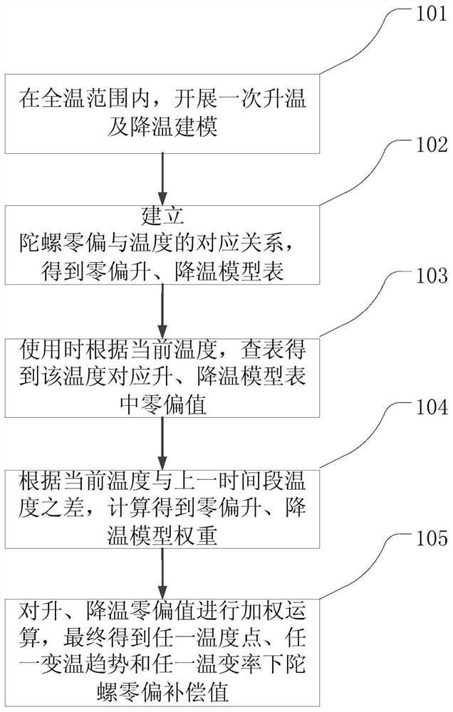
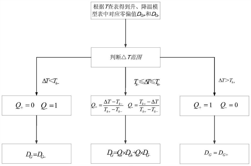
[0074] The present invention provides an embodiment of an optical fiber gyroscope zero bias modeling and compensation method based on the weighting algorithm of the heating and cooling model. The implementation process is shown in figure 1 shown, the compensation algorithm see figure 2 shown, including the following five steps:
Login to View More PUM
 Abstract
The invention relates to a fiber-optic gyroscope zero offset determination method. The method comprises the following steps: S1, obtaining a zero-bias temperature rise model table and a zero-bias temperature drop model table under a preset temperature change rate; s2, querying a zero-bias heating model table and a zero-bias cooling model table, and obtaining a heating zero-bias value and a cooling zero-bias value corresponding to the current environment temperature of the tested fiber-optic gyroscope; s3, calculating a zero-bias heating model weight and a zero-bias cooling model weight corresponding to the current temperature; and S4, carrying out weighted operation on the temperature rise zero-bias value and the temperature drop zero-bias value corresponding to the current temperature obtained in the step S2, and finally obtaining the gyroscope zero-bias value of the fiber-optic gyroscope at the current environment temperature and the temperature change rate. The weighted zero-bias compensation value can be calculated in real time according to the temperature, the temperature rising and falling trend and the temperature change rate, the problem that a traditional zero-bias compensation method is poor in environmental adaptability is solved, and the method is suitable for zero-bias modeling and compensation of fiber-optic gyroscopes of different models or precisions.
Description
technical field [0001] The invention relates to a method for determining the zero bias of an optical fiber gyroscope, which belongs to the technical field of optical fiber gyroscopes. Background technique [0002] Gyroscopes are an essential part of inertial systems and are used to measure the angular velocity of a vehicle. Compared with traditional mechanical gyroscopes, fiber optic gyroscopes are designed based on the Sagnac effect without any moving parts. Therefore, this new all-solid-state gyroscope has many advantages such as small size, light weight, high precision, low cost, high reliability, and long life, and has been widely used in military and civilian fields. Fiber optic gyroscopes are sensitive to changes in ambient temperature, and will produce non-reciprocal phase errors with changes in ambient temperature, which will cause the zero position of the fiber optic gyroscope to drift. Therefore, it is necessary to compensate for the drift of the fiber optic gyro...
Claims
Login to View More Application Information
Patent Timeline
 Patent Type & AuthorityApplications(China)
IPC IPC(8): G01C19/72
CPCG01C19/726
Inventor葛宏升孟祥涛汤梦希向政黄磊王宁左明璐刘佳
OwnerBEIJING AEROSPACE TIMES OPTICAL ELECTRONICS TECH