Permanent magnet bias inductor tuning device and method with parallel magnetic circuits

A permanent magnet bias and tuning device technology, applied in the direction of transformer/inductor magnetic core, continuously variable inductor/transformer, preventing/reducing unnecessary electric/magnetic influence, etc., can solve the problem that DC control cannot be realized Efficient use of coils, inability to adjust the magnetic flux density of the middle core, and insignificant changes in magnetic permeability, etc., to achieve the effects of weakening the core operating point offset, expanding the inductance adjustment range, and optimizing the adjustment effect

Pending Publication Date: 2021-11-12
SOUTHEAST UNIV
View PDF8 Cites 0 Cited by
  • Summary
  • Abstract
  • Description
  • Claims
  • Application Information

AI Technical Summary

Problems solved by technology

However, through the analysis of the characteristics of the magnetization curve, it can be seen that the magnetic permeability of the area adjacent to the saturation region of the magnetization curve does not change significantly. To adjust the magnetic flux density of the magnetic core around this working point requires a large DC control current, which cannot be realized for the DC control coil. efficient use of
At the same time, the magnetic flux density of the middle magnetic core cannot be adjusted by using double E-shaped magnetic cores, and there is a certain degree of material waste

Method used


Image

  • Permanent magnet bias inductor tuning device and method with parallel magnetic circuits
  • Permanent magnet bias inductor tuning device and method with parallel magnetic circuits
  • Permanent magnet bias inductor tuning device and method with parallel magnetic circuits

Examples


Embodiment Construction

[0029] Below in conjunction with accompanying drawing, technical scheme of the present invention is described in further detail:

[0030] This invention may be embodied in many different forms and should not be construed as limited to the embodiments set forth herein. Rather, these embodiments are provided so that this disclosure will be thorough and complete, and will fully convey the scope of the invention to those skilled in the art.

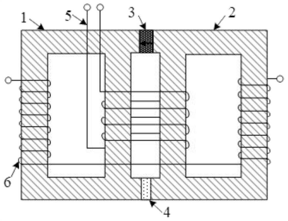
[0031] Such as figure 1 as shown, figure 1 It is a schematic diagram of the overall structure of a permanent magnet bias inductance tuning device with a parallel magnetic circuit proposed by the present invention. The device includes a left magnetic core 1, a right magnetic core 2, a permanent magnet 3, an air gap 4, an inductance tuning coil 5, a DC Control coil 6;

[0032] Among them, the left magnetic core 1 and the right magnetic core 2 are placed side by side, the permanent magnet 3 and the air gap 4 are arranged between the left magn...


PUM


Abstract

The invention discloses a permanent magnet bias inductance tuning device with parallel magnetic circuits. The device comprises a left magnetic core, a right magnetic core, a permanent magnet, an air gap, an inductance tuning coil and a direct current control coil, wherein the left magnetic core and the right magnetic core are arranged side by side, the permanent magnet and the air gap are arranged between the left magnetic core and the right magnetic core, the permanent magnet forms a closed inner side magnetic circuit in inner side arms of the left magnetic core and the right magnetic core according to the excitation direction, and the direct current control coil is formed by connecting two windings on outer side arms of the left magnetic core and the right magnetic core in series. The magnetomotive force of the direct current control coil forms a closed outer magnetic circuit in the left magnetic core and the right magnetic core, and the inductance tuning coils are arranged on the inner side arms of the left magnetic core and the right magnetic core. The excitation current of the direct current control coil required for adjusting the state of the magnetic core when the device works is reduced, the direct current control power and the loss caused by the direct current control power are effectively reduced, meanwhile, the influence of a load on the work of the inductance tuning device is reduced, and the working stability of the inductance tuning device is improved.

Description

technical field [0001] The invention relates to the technical field of inductance tuning devices, in particular to a permanent magnet bias inductance tuning device and method with a parallel magnetic circuit. Background technique [0002] With the development of power electronics technology, high-frequency resonant converters have been widely used in various industrial occasions, such as wireless charging (energy transmission) devices, plasma generators, bidirectional DC / DC power supplies, power electronic transformers, etc. Resonant converters generally require the operating frequency to be in a resonant or quasi-resonant state, that is, the operating frequency is equal to or close to the resonant frequency of the converter. If this condition cannot be met, the energy transmission efficiency will drop sharply. However, it is difficult to ensure that the resonant inductance and capacitance of the resonant converter are completely consistent during mass production, and long-t...

Claims


Application Information

Patent Timeline
Patent Type & Authority Applications(China)
IPC IPC(8): H01F27/24H01F27/34H01F27/28H01F21/02
CPCH01F27/24H01F27/34H01F27/28H01F21/02
Inventor 张建忠王丽赵进邓富金
Owner SOUTHEAST UNIV
Why Eureka
Try Eureka