
Special oil-immersed energy-saving transformer for three-phase oil field

An energy-saving transformer and special oil technology, applied in the direction of transformers, variable transformers, transformer/inductor components, etc., can solve the problems of unbalanced current on the high-voltage side of the transformer, reduce the utilization rate of the front-end transformer, and large equipment investment, etc., to achieve Multiple tap positions, reduced equipment investment and large conductor cross-section

Pending Publication Date: 2021-11-12
青州市长城电力变压器股份有限公司
View PDF0 Cites 0 Cited by
  • Summary
  • Abstract
  • Description
  • Claims
  • Application Information

AI Technical Summary

Problems solved by technology

[0003] In order to solve the above technical problems, the present invention provides a special oil-immersed energy-saving transformer for three-phase oil fields, to solve the problem that two or three transformers are required in total for the existing oil field exploitation, because the current on the high-voltage side of the transformer is extremely unbalanced when carrying a single-phase load. , reducing the utilization rate of the front-stage transformer, and the phenomenon of "big horse-drawn carts" has resulted in the problems of large equipment investment, large floor area and low utilization rate

Method used


Image

  • Special oil-immersed energy-saving transformer for three-phase oil field
  • Special oil-immersed energy-saving transformer for three-phase oil field
  • Special oil-immersed energy-saving transformer for three-phase oil field

Examples


Embodiment Construction

[0016] In order to enable those skilled in the art to better understand the present invention, the following will clearly and completely describe the technical solutions in the embodiments of the present invention. Obviously, the described embodiments are only a part of the present invention, rather than Full examples. Based on the embodiments of the present invention, all other embodiments obtained by persons of ordinary skill in the art without making creative efforts shall fall within the protection scope of the present invention.

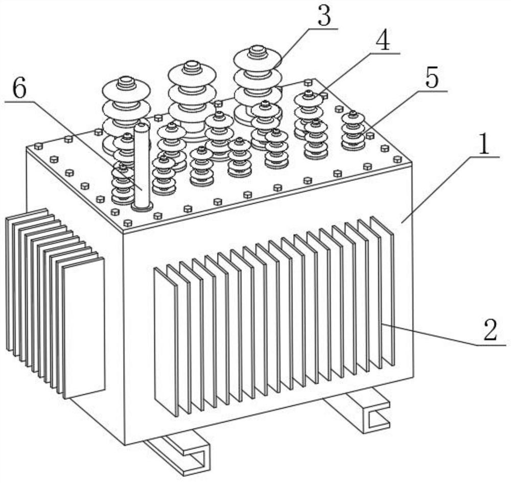
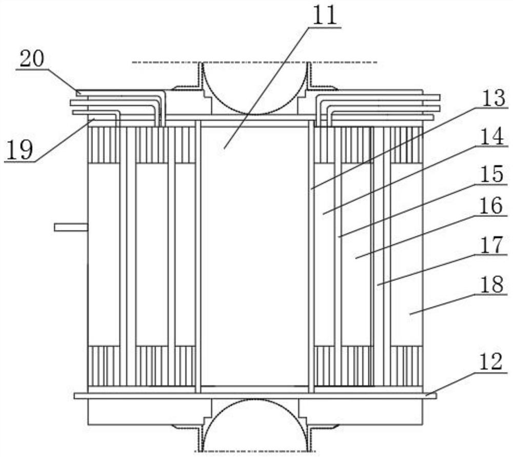
[0017] as attached figure 1 to attach figure 2 shown.

[0018] Three-phase oil-immersed energy-saving transformer for oil fields, including an oil tank 1, heat sinks 2 are arranged on both sides of the oil tank 1, high-voltage bushings 3 are arranged on the upper surface of the oil tank 1, and the upper surface of the oil tank 1 is located on the upper surface of the oil tank 1. One side of the high-voltage bushing 3 is provided with a mediu...


PUM


Abstract

A special oil-immersed energy-saving transformer for a three-phase oil field comprises an oil tank. Cooling fins are arranged on the two sides of the oil tank respectively, a high-voltage sleeve is arranged on the upper surface of the oil tank, and a medium-voltage sleeve and a low-voltage sleeve are sequentially arranged on the upper surface of the oil tank and located on one side of the high-voltage sleeve. An oil level gauge is arranged on one side of the low-voltage sleeve and located on the upper surface of the oil tank. A transformer iron core is arranged in the middle of the interior of the oil tank, and a lower insulating plate is arranged between the lower surface of the transformer iron core and the bottom surface of the interior of the oil tank; and the upper surface of the lower insulating plate and the periphery of the transformer iron core are wrapped with an insulator, and the periphery of the insulator is provided with a low-voltage coil. A traditional conventional transformer and a single-phase oil field special transformer are combined into a whole, the problems that when a single-phase transformer is loaded, a high-voltage current is unbalanced, the utilization rate of a preceding-stage transformer is low, and the occupied area is large are solved, and the equipment investment and the transformer operation cost are reduced.

Description

technical field [0001] The invention belongs to the technical field of oil-immersed transformers, in particular to oil-immersed energy-saving transformers specially used for three-phase oil fields. Background technique [0002] Exploitation of heavy oil, high wax content and high freezing point reservoirs requires electric heating rods to be heated, and the required voltage is adjusted according to actual conditions, so a single-phase voltage regulating transformer is needed to provide power for the electric heating rods. Heavy oil, high wax content and high freezing point reservoirs require a conventional transformer and a single-phase voltage-regulating transformer. A total of two or three transformers are needed to realize the realization, because the current on the high-voltage side of the transformer is extremely low when there is a single-phase load. Balance, reducing the utilization rate of the front-stage transformer, there is a phenomenon of "big horses and small ca...

Claims


Application Information

Patent Timeline
Patent Type & Authority Applications(China)
IPC IPC(8): H01F27/28H01F27/29H01F27/32H01F29/04
CPCH01F27/28H01F27/324H01F27/29H01F29/04
Inventor 田树民田怡孙智超
Owner 青州市长城电力变压器股份有限公司
Learn More