
Polarized antenna with reconfigurable directional diagram

A pattern and antenna technology, applied to antennas, resonant antennas, antenna grounding devices, etc., can solve the problems of large antenna volume, antenna matching and radiation performance effects, and achieve the effect of high gain, low profile, and small antenna volume

Active Publication Date: 2021-11-12
NANJING UNIV OF INFORMATION SCI & TECH
View PDF10 Cites 3 Cited by
  • Summary
  • Abstract
  • Description
  • Claims
  • Application Information

AI Technical Summary

Problems solved by technology

As an important part of the wearable system, the wearable antenna works near the human wrist with high dielectric constant and high loss tangent. The matching and radiation performance of the antenna will be seriously affected; and most of the existing wearable antennas are directional Radiation, in order to reduce the impact of antenna radiation on the human body, a metal reflector is generally placed at a quarter of the wavelength below the antenna, resulting in a larger volume of the antenna

Method used


Image

  • Polarized antenna with reconfigurable directional diagram
  • Polarized antenna with reconfigurable directional diagram
  • Polarized antenna with reconfigurable directional diagram

Examples


Embodiment Construction

[0020] The technical solutions of the present invention will be described in detail below in conjunction with the accompanying drawings.

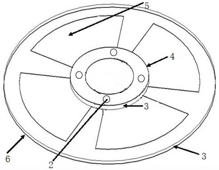
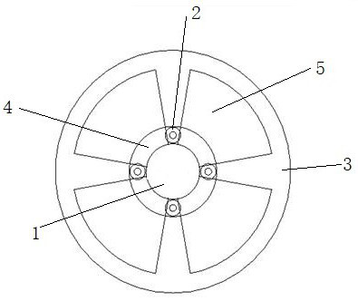
[0021] see Figure 1-3 , the antenna with reconfigurable polarization and pattern of the present invention includes: an upper dielectric board 1, a metal pillar 2, a lower dielectric board 3, a circular loop antenna 4, a fan-shaped metal patch 5, a metal ground 6, and a circular loop antenna 4 is printed on the upper surface of the upper dielectric board 1, and the circular antenna is used as the radiator. The circular antenna 4 is provided with feed ports at angles of α, α+90°, α+180°, and α+270° , the center of the upper dielectric plate 1 and the center of the lower dielectric plate 3 are located on the same axis, and the distance between the upper dielectric plate 1 and the lower dielectric plate 3 is 1 mm, and the matching of the antenna is close to 50 ohms, so that the resonance point of the antenna is at 3.5 At the same time, the an...


PUM

PropertyMeasurementUnit
Radiusaaaaaaaaaa
Thicknessaaaaaaaaaa
Outer ring radiusaaaaaaaaaa

Abstract

The invention discloses a polarized antenna with a reconfigurable directional diagram, and belongs to the technical field of antennas. The antenna comprises an upper-layer dielectric plate, a metal pillar, a lower-layer dielectric plate, a circular antenna, a fan-shaped metal patch and a metal ground, the circular antenna is printed on the upper surface of the upper-layer dielectric plate and is provided with feed ports at the angles of alpha, alpha + 90 degrees, alpha + 180 degrees and alpha + 270 degrees, the circle center of the upper-layer dielectric plate and the circle center of the lower-layer dielectric plate are located on the same axis, the distance between the upper-layer dielectric plate and the lower-layer dielectric plate is 1 mm, the upper-layer dielectric plate and the lower-layer dielectric plate are connected with the feed port through metal supporting columns, four fan-shaped metal patches are printed on the upper surface of the lower-layer dielectric plate, and a metal ground is printed on the lower surface of the lower-layer dielectric plate. According to the antenna, the profile of the antenna can be greatly reduced, the requirement for miniaturization of the wearable antenna is met, and polarization reconfiguration and directional diagram reconfiguration are achieved.

Description

technical field [0001] The invention belongs to the technical field of antennas, in particular to an antenna with reconfigurable polarization and pattern. Background technique [0002] With the rapid development of mobile communication technology, smart antennas are widely considered as a key technology to improve communication quality and spectrum utilization. Smart antennas can adjust the beam to adaptively direct the radio signal to the direction of the user, while the side lobes and null points point to other possible Incoming interference signal. In recent years, polarization and pattern reconfigurable antennas have received extensive attention due to their advantages in increasing channel capacity, suppressing interference, and overcoming multipath fading. In addition, with the advancement of communication technology to 5G in the future, space constraints make compact, low-profile antenna structures more competitive. As an important part of the wearable system, the w...

Claims


Application Information

Patent Timeline
IPC IPC(8): H01Q15/24H01Q1/36H01Q1/48H01Q1/50H01Q9/04H01Q15/14
CPCH01Q15/24H01Q1/36H01Q1/48H01Q1/50H01Q9/0407H01Q15/14Y02D30/70
Inventor 段铸王杰
Owner NANJING UNIV OF INFORMATION SCI & TECH
Learn More