
Mixed gas laser with replaceable filling gas and use method thereof

A technology of mixed gas and gas filling, which is applied to lasers, laser components, phonon exciters, etc., can solve the problems of inconvenient use, affecting processing accuracy, and slow heat dissipation, so as to improve the speed of heat dissipation and increase the efficiency of cooling effect, reducing the effect of overheating

Active Publication Date: 2021-11-12
深圳市光缘实业有限公司
View PDF4 Cites 2 Cited by
  • Summary
  • Abstract
  • Description
  • Claims
  • Application Information

AI Technical Summary

Problems solved by technology

[0002] When the mixed gas laser is running, the laser head will generate heat. If it is not handled properly, the mixed gas laser will be deformed due to excessive heat, which will lead to rapid aging of the laser head. If it is processed at this time, it will seriously affect the processing accuracy, reduce the service life of the mixed gas laser, and cause problems such as poor light quality. Therefore, it is necessary to use a cooling system to cool it down in time to dissipate the heat to ensure the light quality of the laser head. , so it needs to be cooled during cutting
[0003] Most of the existing cooling methods use the laser intermittently to achieve the effect of natural cooling of the laser head during the interval, and some better devices use the jet The way of airflow cools down the laser head, and the device of jet airflow is set inside the laser beam pipe and inside the laser head, which leads to slow heat dissipation and affects the intensity of the laser, which is inconvenient to use

Method used


Image

  • Mixed gas laser with replaceable filling gas and use method thereof
  • Mixed gas laser with replaceable filling gas and use method thereof
  • Mixed gas laser with replaceable filling gas and use method thereof

Examples


Embodiment Construction

[0028] The following will clearly and completely describe the technical solutions in the embodiments of the present invention with reference to the accompanying drawings in the embodiments of the present invention. Obviously, the described embodiments are only some, not all, embodiments of the present invention.

[0029] Examples of the described embodiments are shown in the drawings, wherein like or similar reference numerals designate like or similar elements or elements having the same or similar functions throughout. The embodiments described below by referring to the figures are exemplary and are intended to explain the present invention and should not be construed as limiting the present invention.

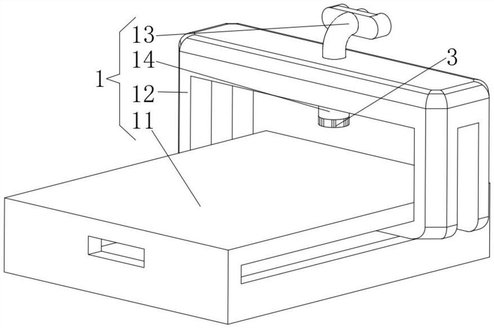
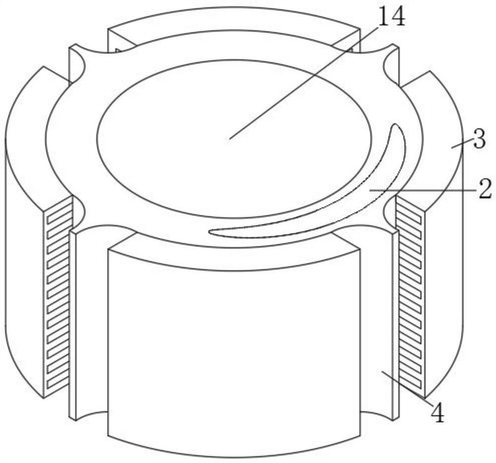
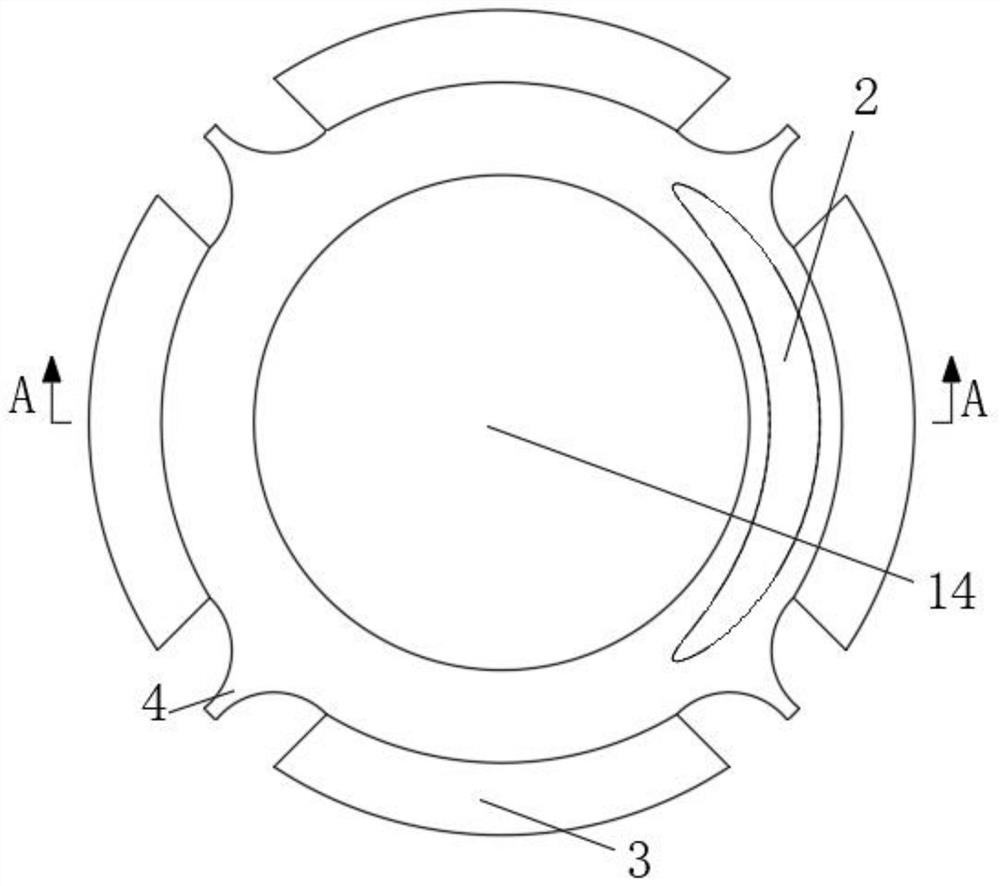
[0030] see Figure 1-5 , the present invention provides a technical solution: a gas-filling replaceable mixed gas laser, including a laser emitting mechanism 1, the outer wall of the laser emitting mechanism 1 is fixedly connected with a liquid cooling mechanism 2, and the o...


PUM


Abstract

The invention discloses a mixed gas laser with a replaceable filling gas and a use method thereof, and relates to the technical field of gas lasers. The mixed gas laser with the replaceable filling gas comprises a laser emitting mechanism, the outer wall of the laser emitting mechanism is fixedly connected with a liquid cooling mechanism, the outer wall of the liquid cooling mechanism is evenly and fixedly connected with an air cooling mechanism, and the outer wall of the air cooling mechanism is fixedly connected with the outer wall of the laser emitting mechanism through the arranged liquid cooling mechanism. An airflow guide block is fixedly connected to the position, close to the air cooling mechanism, of the outer wall of the liquid cooling mechanism. According to the mixed gas laser with the replaceable filling gas and the use method thereof, the laser head part of the laser can be cooled through liquid circulation cooling and air circulation cooling so that the effect of rapid heat dissipation and cooling is achieved, the heat dissipation speed is increased through a method of increasing the heat dissipation area, and the mixed gas laser is relatively convenient to use.

Description

technical field [0001] The invention relates to the technical field of gas lasers, in particular to a gas-filling replaceable mixed gas laser and a method for using the same. Background technique [0002] When the mixed gas laser is running, the laser head will generate heat. If it is not handled properly, the mixed gas laser will be deformed when it is overheated, resulting in rapid aging of the laser head. If it is processed at this time, it will seriously affect the processing accuracy and reduce the mixing. The service life of the gas laser has problems such as poor light quality, so it is necessary to use a cooling system to cool it down in time to dissipate the heat to ensure the light quality of the laser head, so it needs to be cooled during cutting. [0003] Most of the existing cooling methods are to use the laser intermittently to make the laser head achieve the effect of natural cooling during the intermittent period. Some better devices cool down the laser head ...

Claims


Application Information

Patent Timeline
Patent Type & Authority Applications(China)
IPC IPC(8): H01S3/041
CPCH01S3/041H01S3/0407H01S3/0404H01S3/0405
Inventor 陈艳惠
Owner 深圳市光缘实业有限公司
Learn More