
Photonic crystal surface emitting type laser structure

A photonic crystal and laser structure technology, which is applied in the direction of semiconductor lasers, lasers, phonon exciters, etc., can solve the problem of excessive divergence angle and threshold current, and achieve the effect of reducing divergence angle and threshold current

Pending Publication Date: 2021-11-12
INTERFACE TECH CHENGDU CO LTD +3
View PDF5 Cites 0 Cited by
  • Summary
  • Abstract
  • Description
  • Claims
  • Application Information

AI Technical Summary

Problems solved by technology

As far as the existing laser structure is concerned, there are problems that the divergence angle (divergence angle) is too large and the threshold current is too large, which need to be solved

Method used


Image

  • Photonic crystal surface emitting type laser structure
  • Photonic crystal surface emitting type laser structure
  • Photonic crystal surface emitting type laser structure

Examples


Embodiment Construction

[0042] In order to make the description of the present disclosure more detailed and complete, reference may be made to the drawings and various implementations described below. Elements in the drawings are not drawn to scale and are provided merely to illustrate the present disclosure. Numerous practical details are described below in order to provide a thorough understanding of the present disclosure, however, those of ordinary skill in the relevant art will understand that the present disclosure can be practiced without one or more of the practical details, and thus, these details are not apply to define this disclosure.

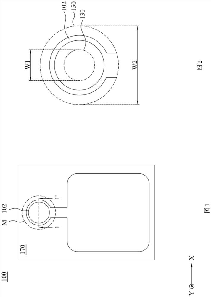
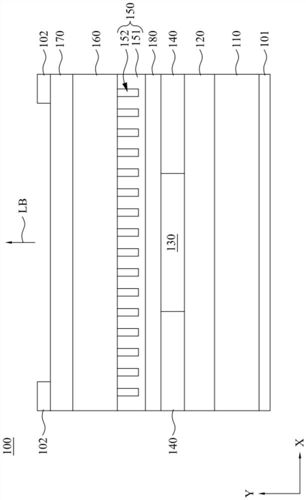
[0043] Please refer to Figure 1 to Figure 3 . figure 1 To illustrate a top view of a photonic crystal surface-emitting laser structure 100 according to an embodiment of the present disclosure, figure 2 for illustration figure 1 An enlarged perspective view of the shown photonic crystal surface-emitting laser structure 100 in the region M, image 3 b...


PUM

PropertyMeasurementUnit
lengthaaaaaaaaaa

Abstract

A photonic crystal surface emitting type laser structure comprises a substrate, an N-type cladding layer, an active layer, a refractive index matching layer and a photonic crystal structure. The N-type coating layer is arranged on the substrate. The active layer is disposed on the N-type cladding layer. The refractive index matching layer is disposed on the N-type cladding layer and surrounds the active layer. The refractive index matching layer is electrically insulated, and the effective refractive index of the refractive index matching layer is substantially the same as the effective refractive index of the active layer. The photonic crystal structure is disposed on the active layer and the refractive index matching layer. By means of the structural configuration, the divergence angle and the threshold current of the laser can be reduced.

Description

technical field [0001] This disclosure relates to a photonic crystal surface-emitting laser structure. Background technique [0002] Lasers are widely used in fields such as medical treatment, optical communication and industrial processing. As far as the existing laser structure is concerned, there are problems of too large divergence angle and too large threshold current, which need to be solved. Contents of the invention [0003] In view of this, one purpose of the present disclosure is to propose a photonic crystal surface-emitting laser structure with a small divergence angle and a small threshold current. [0004] To achieve the above object, according to some embodiments of the present disclosure, a photonic crystal surface-emitting laser structure includes a first substrate, an N-type cladding layer, an active layer, a refractive index matching layer, and a photonic crystal structure. The N-type cladding layer is disposed on the first substrate. The active layer...

Claims


Application Information

Patent Timeline
Patent Type & Authority Applications(China)
IPC IPC(8): H01S5/183
CPCH01S5/18322H01S5/18377H01S5/11H01S5/04254H01S2301/18H01S5/185H01S5/2009H01S5/04253H01S5/227H01S5/2218H01S5/2224H01S5/2072H01S5/04256H01S5/343
Inventor 卢廷昌洪国彬陈立人赵天行
Owner INTERFACE TECH CHENGDU CO LTD
Learn More