
Surface emitting laser luminescent diode structure

Active Publication Date: 2019-10-31
HIGH POWER OPTO
View PDF0 Cites 0 Cited by
  • Summary
  • Abstract
  • Description
  • Claims
  • Application Information

AI Technical Summary

Benefits of technology

The present invention is a surface emitting laser luminescent diode structure with a small divergence angle of light and a high operating speed. The reflecting mirror is placed on a protective layer along the surface of the recess and completely covers the laser cavity region, reducing the divergence angle of light and preventing lateral light leakage. A current isolating layer is also placed on the reflecting mirror to improve reflectance and limit current flow direction, increasing the response speed.

Problems solved by technology

Thus, it is hard to meet the user's requirement on the reflectance.
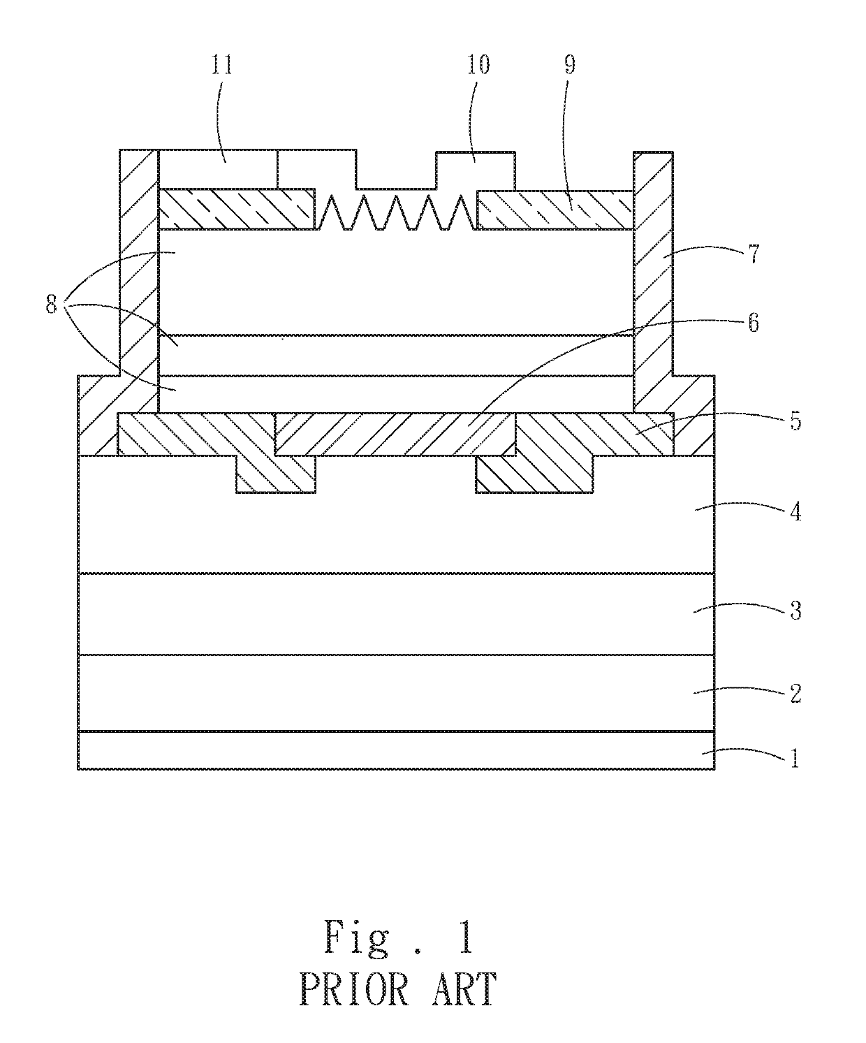
Besides, the impressed current distribution layer 5 also needs to be a large area in order to control a flow direction of the current, thereby the effective area of the lower reflecting layer 6 is hard to increase and fails to form a favorable resonant cavity accordingly.
In addition, such a traditional structure design does not generate a real vertical light source, and signals are prone to significant attenuation due to the long-distance transmission, thereby failing to satisfy the user's needs.

Method used


Image

  • Surface emitting laser luminescent diode structure
  • Surface emitting laser luminescent diode structure
  • Surface emitting laser luminescent diode structure

Examples


Embodiment Construction

[0017]The detailed description and technical content of the present invention will now be described with reference to the accompanying drawings as follows.

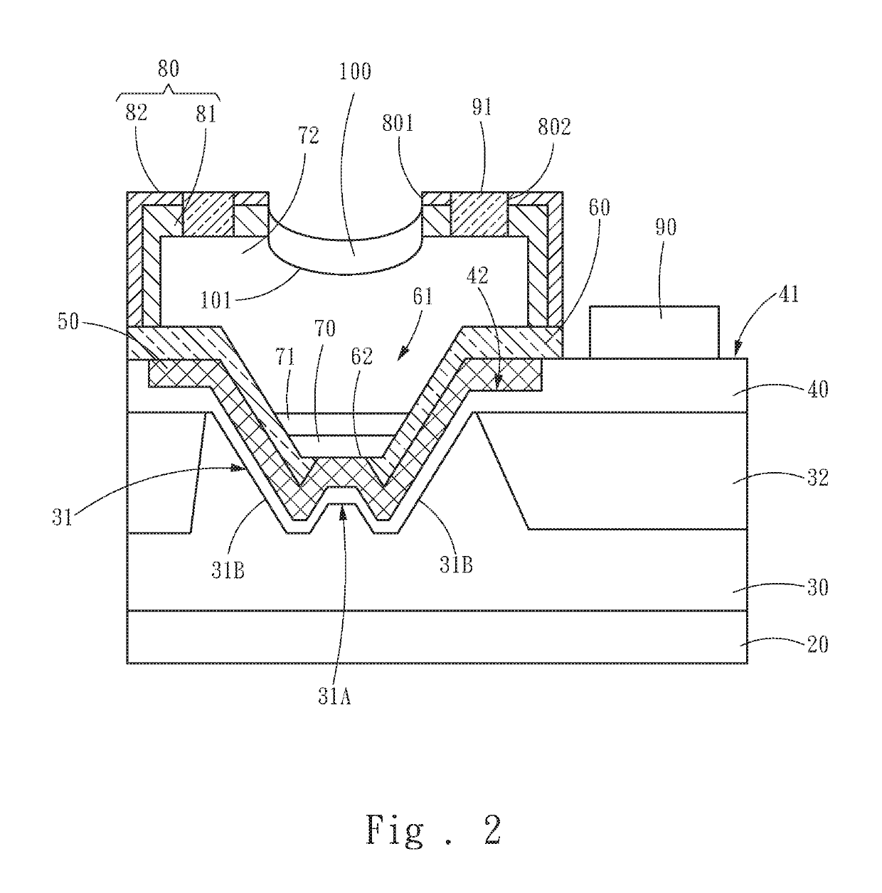
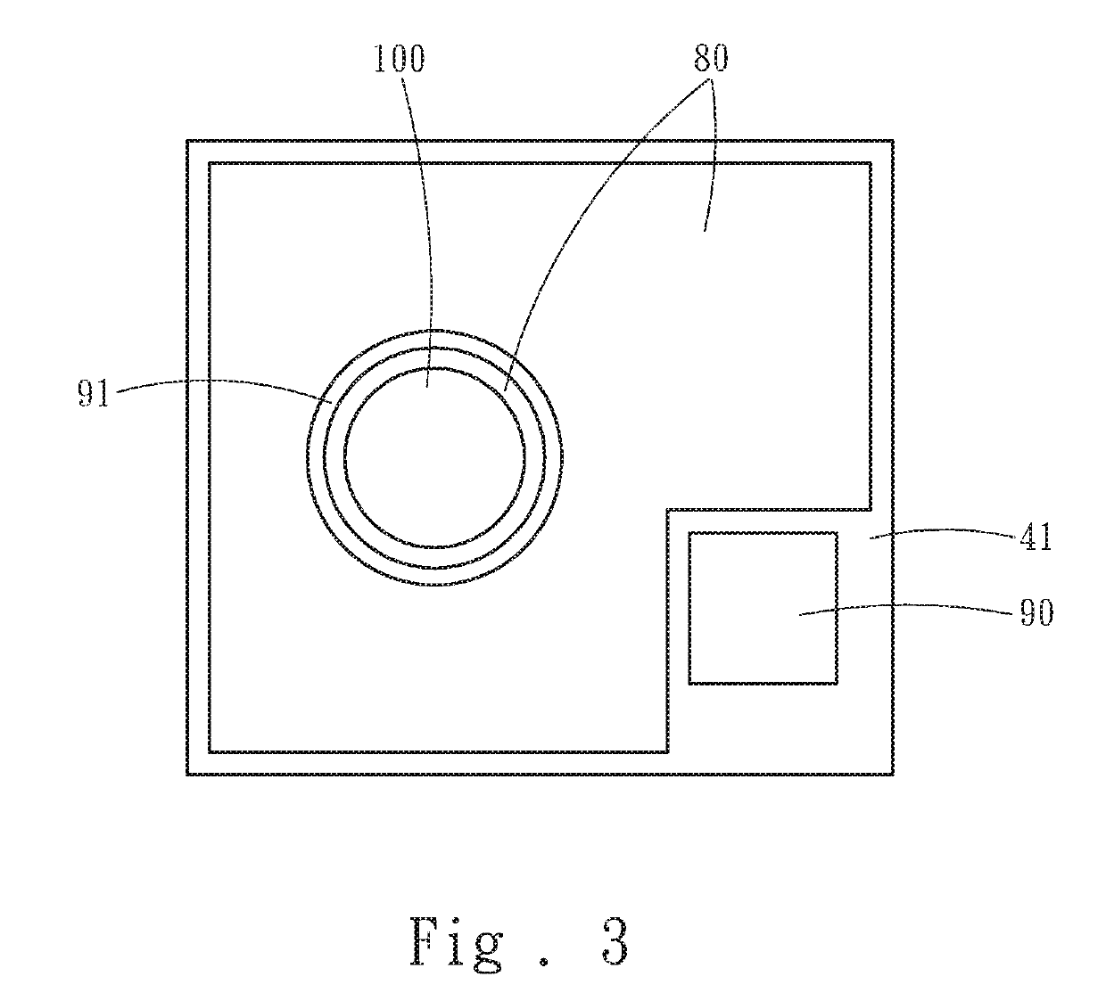
[0018]Referring to FIG. 2 and FIG. 3, the present invention relates to a surface emitting laser luminescent diode structure including a thermal conductivity insulating substrate 20, a bonding layer 30, a protective layer 40, a reflecting mirror 50, a current isolating layer 60, a P-type semiconductor 70, a luminescent diode 71, an N-type semiconductor 72, an upper reflecting layer 80, a P-type electrode 90, an N-type electrode 91, and a band-pass layer 100.

[0019]In one embodiment, the bonding layer 30 is disposed on the thermal conductivity insulating substrate 20 and comprises a recess 31. The recess 31 comprises two tilted slopes 31B on two sides, and a trapezoidal cylinder 31A located and protruding from a bottom center of the recess 31. A basal area of the trapezoidal cylinder 31A is smaller than a basal area of the recess 31....


PUM


Abstract

The present invention is a surface emitting laser luminescent diode structure which is characterized in that a recess comprises two tilted slopes on two sides and a protruding trapezoidal cylinder located at the bottom center of the recess is disposed at the bottom of a laser resonant cavity. Thus, a reflecting mirror disposed along the surface of the recess includes two tilted side surfaces as leak-proof sides, which reduces the divergence angle and avoid the lateral light leakage. Additionally, a current isolating layer is disposed on the reflecting mirror and is designed to satisfy the condition (¼*wavelength*1 / refractive index) of an optical film, thereby allowing the reflecting mirror to receive an excellent reflectance. Besides, the current isolating layer limits the flow direction of the current, thus increasing operating speed.

Description

FIELD OF THE INVENTION[0001]The present invention relates to a surface emitting laser luminescent diode, and more particularly to a structure of the surface emitting laser luminescent diode structure.BACKGROUND OF THE INVENTION[0002]Surface Emitting Laser (SEL) is a semiconductor structure of which laser is emitted perpendicularly to a top surface, for example, the Taiwan patent No. I268031 entitled “Vertical Cavity Surface Emitting Laser and Method for Fabricating the Same” and the Taiwan patent No. I403050 entitled “Vertical Cavity Surface Emitting Laser (VCSEL), VCSEL Array Device, Optical Scanning Apparatus, and Image Forming Apparatus”.[0003]Referring to FIG. 1, a traditional surface emitting laser structure includes a P-type electrode 1, a substrate 2, a bonding layer 3, a stress release layer 4, an impressed current distribution layer 5, a lower reflecting layer 6, a passivation layer 7, a luminescent diode layer 8, an upper reflecting layer 9, a band-pass layer 10, and an N-...

Claims


Application Information

Patent Timeline
IPC IPC(8): H01S5/183
CPCH01S5/18344H01S5/18308H01S5/18361H01S5/18369H01S5/18341H01S5/18352H01S5/18394H01S5/18322H01S5/02461H01S5/04254H01S5/04257H01S5/18375H01S5/18391H01S2301/173
Inventor YEN, WEI-YUCHOU, LI-PINGWU, TAU-JINCHANG, CHIH-SUNG
Owner HIGH POWER OPTO
Learn More