
Manufacturing method and manufacturing apparatus for hollow structure of image display element

a manufacturing method and manufacturing apparatus technology, applied in the direction of identification means, instruments, other domestic objects, etc., can solve the problems of not being able to save the displayed image, the device is not easy to carry around all the time, and the human eye may become fatigued, etc., to achieve excellent reflectance and contrast

Active Publication Date: 2012-09-25
TRANSCEND OPTRONICS (YANGZHOU) CO LTD
View PDF16 Cites 0 Cited by
  • Summary
  • Abstract
  • Description
  • Claims
  • Application Information

AI Technical Summary

Benefits of technology

"The patent text describes a method and apparatus for manufacturing an image display element structure and an electrophoretic image display element with excellent reflectance and contrast. The method involves coating a substrate surface with a plastic-deformable material that maintains spaces in recessed portions on the substrate surface, expanding the material to form gaps in the spaces, and peeling off the material in which the gaps have been formed. The apparatus includes a coating unit, an expanding unit, and a peeling unit. The technical effects of this patent text are improved manufacturing efficiency and quality of image display elements."

Problems solved by technology

However, these devices are not easy to carry around all the time.
Furthermore, as these devices are self-luminous devices, they are disadvantageous in that human eyes may become fatigued by usage over a long period of time.
Another disadvantage is that the displayed image cannot be saved if the power is turned off.
Some paper sheets can be recycled, but recycling paper requires a tremendous amount of work and cost, which are problematic in terms of saving resources.
Hence, the precursor may not sufficiently enter the recessed portions such that the shape is not precisely transferred.
Furthermore, when the intensity of the precursor is insufficient, some of the precursor may remain in the recessed portions of the die when the precursor is removed.
Accordingly, it is difficult to form a honeycomb structure with hollow bodies with this method.
However, because the radiation light wraps around or scatters in the radiation curing layer, it is difficult to create walls of high aspect ratios.

Method used


Image

  • Manufacturing method and manufacturing apparatus for hollow structure of image display element
  • Manufacturing method and manufacturing apparatus for hollow structure of image display element
  • Manufacturing method and manufacturing apparatus for hollow structure of image display element

Examples


first embodiment

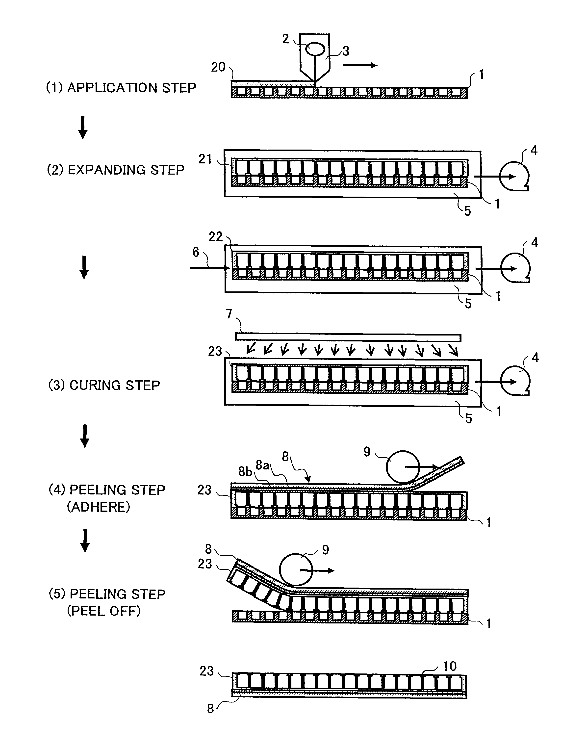
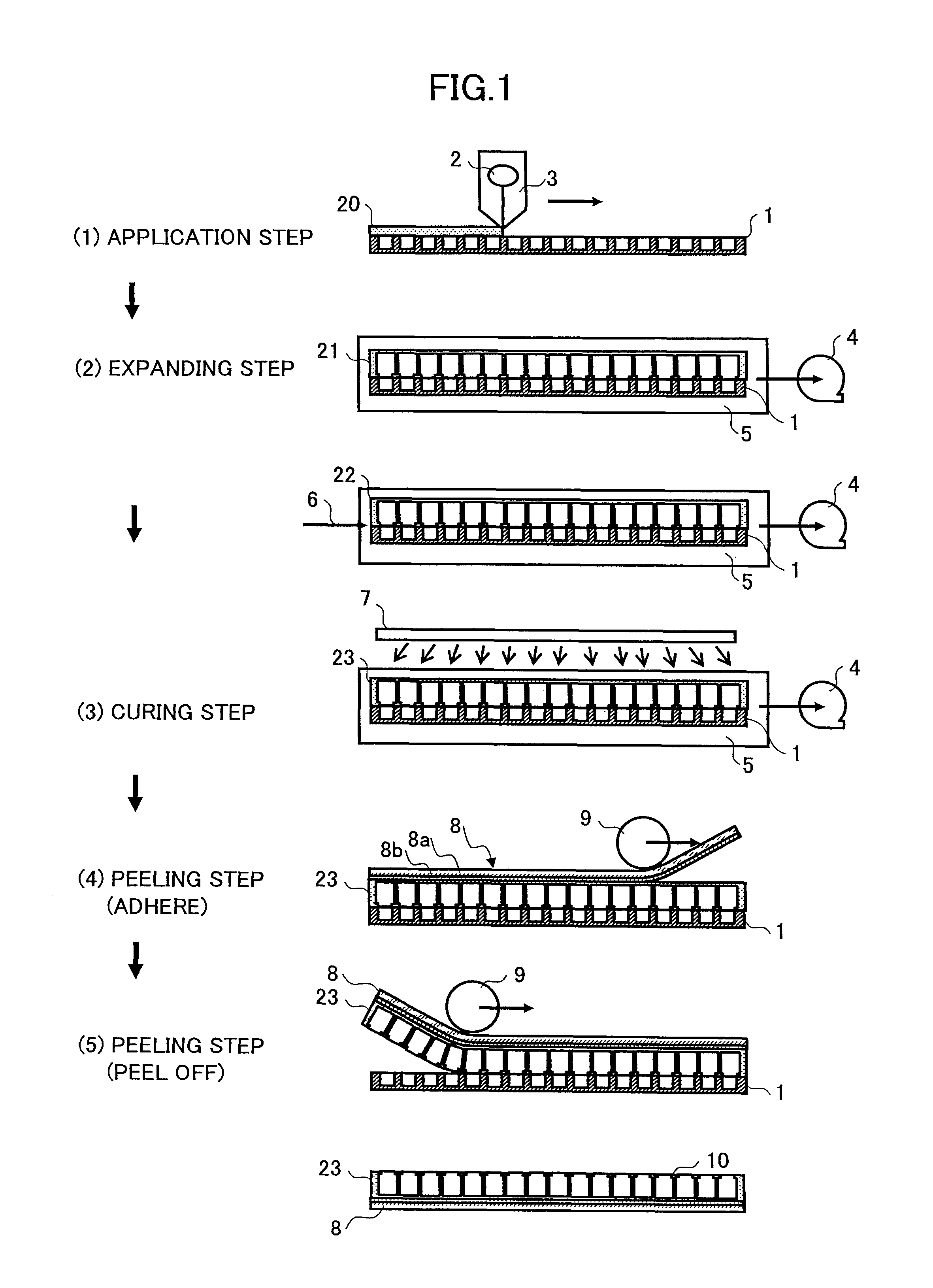
[0027]A description is given of a manufacturing method and a manufacturing apparatus for an image display element structure according to the first embodiment, with reference to the manufacturing process chart shown in FIG. 1.

[0028]In (1) an application step, a material 2 is applied, with an applying device 3, onto a substrate 1 having plural recessed portions arranged at predetermined intervals, maintaining a space in each of the recessed portions. This material 2 is capable of plastic deformation, and is used for forming hollow structures to be used for the image display elements. The applying device 3 is preferably capable of applying the plastic-deformable material 2 without causing the material 2 to enter the recessed portions on the substrate 1. The applying device 3 shown in FIG. 1 employs a slit coating method. Specifically, the plastic-deformable material 2 is supplied, at a constant speed, to a slit that extends lengthwise in the application width direction of the applying ...

second embodiment

[0035]With reference to FIG. 3, a description is given of a continuous manufacturing apparatus 30 for an image display element structure (the cured sheet 22), which is fabricated with a plastic-deformable material that is a specific water soluble resin. The manufacturing apparatus 30 includes a temperature / humidity control chamber 31, a decompression chamber 32, a decompression drying chamber 33, a pressure raising chamber 34, and a peeling device 35. The water soluble resin used as a plastic-deformable material 38 is gelatin MC-243 manufactured by Jellice Co., Ltd. The gelatin is dissolved with pure water to around 5 wt % through 30 wt %, thereby forming a gelatin water solution.

[0036]This gelatin water solution is evenly applied onto a substrate 37 with a slit coater acting as an applying device 39, in such a manner that the gelatin water solution has a thickness of 40 μm through 50 μm. The substrate 37 has recessed portions arranged in a staggered manner at 60 degrees at pitches ...

third embodiment

[0042]A description is given of a method of manufacturing an image display element structure according to a third embodiment of the present invention that is similar to that of the second embodiment. The (1) application step in FIG. 1 involved applying the water soluble material 2 onto the substrate 1 with plural predetermined recessed portions, which substrate 1 is bonded onto a glass plate with favorable flatness. Upon controlling the temperature of the water soluble material 2, the water soluble material 2 is sent out onto the substrate 1 from the applying device 3 including a discharging pump, and at the same time the substrate 1 is moved so that a uniform film is formed on the substrate 1. The film is formed in such a manner as to maintain spaces in the recessed portions on the substrate 1. A solution, which is obtained by diluting gelatin MC-243 (manufactured by Jellice Co., Ltd.) with pure water by four through five times, is used as the water soluble material 2. The water so...


PUM

PropertyMeasurementUnit
thicknessaaaaaaaaaa
heightaaaaaaaaaa
thicknessaaaaaaaaaa

Abstract

A disclosed method of manufacturing an image display element structure includes a coating step of coating a substrate surface including a plurality of recessed portions arranged at predetermined intervals, with a coating material that is plastic-deformable, in such a manner as to maintain spaces in the recessed portions; and an expanding step of forming gaps in the coating material coating the substrate surface by expanding gas in the spaces, wherein the gaps correspond to the recessed portions; and a peeling step of peeling off the coating material in which the gaps have been formed, from the substrate surface.

Description

TECHNICAL FIELD[0001]The present invention relates to a manufacturing method and a manufacturing apparatus for an image display element structure, and a manufacturing method and a manufacturing apparatus for an electrophoretic image display element employing the same.BACKGROUND ART[0002]CRTs and liquid crystal displays are widely used as terminals for displaying images such as characters, still images, and video images. With these devices, digital data can be instantaneously displayed and rewritten. However, these devices are not easy to carry around all the time. Furthermore, as these devices are self-luminous devices, they are disadvantageous in that human eyes may become fatigued by usage over a long period of time. Another disadvantage is that the displayed image cannot be saved if the power is turned off. Meanwhile, in order to distribute the characters and still images or to save them as documents, they are recorded onto a paper medium with a printer. A paper medium is widely ...

Claims


Application Information

Patent Timeline
Patent Type & Authority Patents(United States)
IPC IPC(8): B29C44/20G02F1/167G02F1/1679
CPCG02F1/167G09F9/372G02F2001/1672G02F1/1681G02F1/1679
Inventor OHSHIMA, HISAYOSHIOHGAKI, MASARUKANEMATSU, TOSHIHIROMASUZAWA, MASAHIROSENO, SHINYAAOKI, SHINJI
Owner TRANSCEND OPTRONICS (YANGZHOU) CO LTD
Learn More