Split type twisted cable twist stopping device and assembling method

A split and twisted cable technology, which is applied in the direction of cable installation, cable layout between relative moving parts, cable laying equipment, etc., can solve problems affecting cable life, long installation time, alternating load force, etc., and achieve reduction The effect of relative friction damage, improving service life and avoiding lateral impact force

Active Publication Date: 2021-11-12
库珀新能源股份有限公司
View PDF8 Cites 0 Cited by
  • Summary
  • Abstract
  • Description
  • Claims
  • Application Information

AI Technical Summary

Problems solved by technology

[0004] At present, there are two forms of cable laying in wind turbines, one is top-down laying, and the other is bottom-up laying. The first laying method only needs to lower the cable. The anti-twist mechanism of the cable needs to pass the anti-twist inner ring and the anti-twist outer ring on the cable from the top of the cable. During the threading process, it is easy to rub against the cable and affect the life of the cable. If the cable is laid from bottom to top, the above-mentioned cables will stop. The torsion mechanism is threaded from the bottom end of the cable, and the cable under the inner ring of the torsion stop needs to be straightened out before the threading, which takes a long time to install; When the cable swings, the cable fixed by the anti-twist inner ring may be bent, resulting in alternating load force from left to right and affecting the life of the cable

Method used


Image

  • Split type twisted cable twist stopping device and assembling method
  • Split type twisted cable twist stopping device and assembling method
  • Split type twisted cable twist stopping device and assembling method

Examples


Embodiment Construction

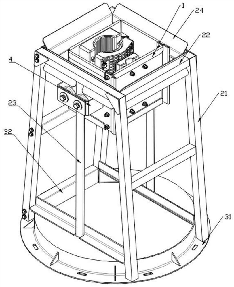
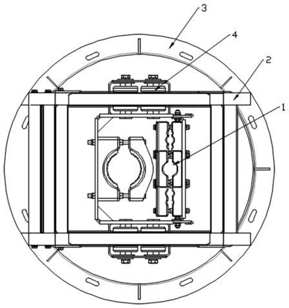
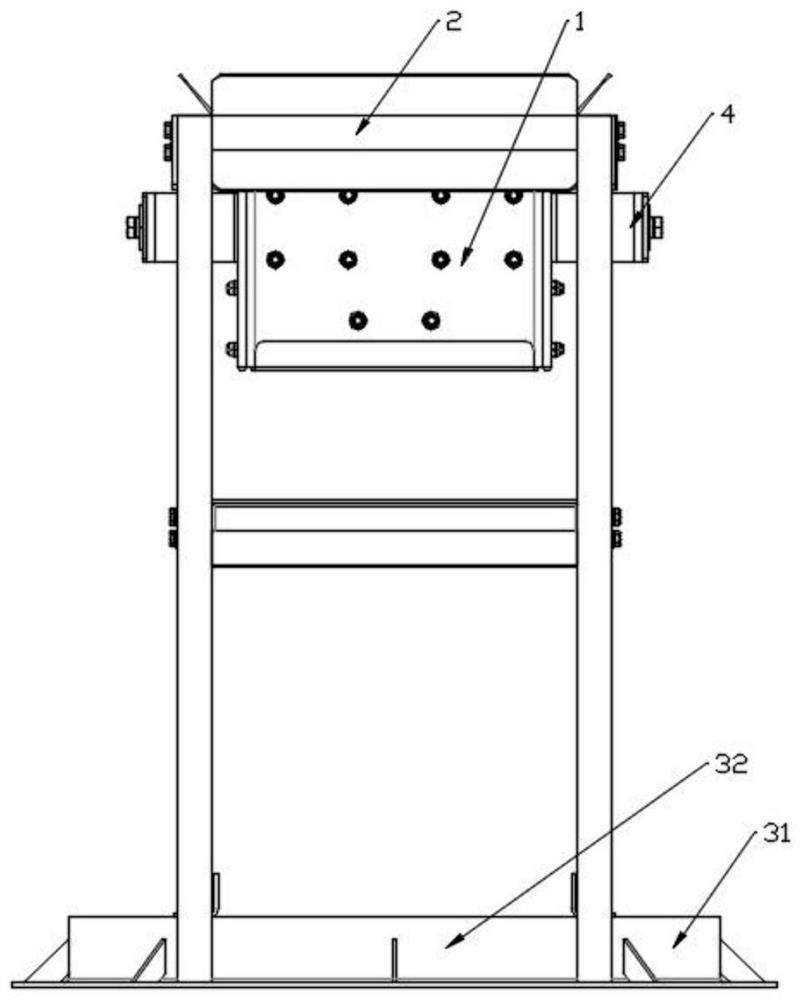
[0032] Below in conjunction with accompanying drawing, the present invention is made further embodiment. Based on the embodiments of the present invention, all other embodiments obtained by persons of ordinary skill in the art without creative efforts fall within the protection scope of the present invention.

[0033] As shown in the figure, this embodiment provides a split-type twisted cable anti-twist device, including a partition assembly 1, a guide pulley group 4 and a fixed bracket 2. The partition assembly 1 is used to limit the rotation of the twisted cable and can move along with the twisted cable. The twisted cable moves in the axial direction, the bottom of the fixed bracket 2 is fixedly connected to the saddle platform at the bottom of the tower through the split flange 3, a cable suspension section of a certain length is arranged under the saddle platform, and the partition assembly 1 is arranged on the left and right sides. The guide pulley group 4 slides along th...


PUM


Abstract

The invention provides a split type twisted cable twist stopping device, which comprises a separation assembly, guide pulley sets and a fixing bracket, wherein the separation assembly slides on a sliding rod arranged on the fixing bracket in the axial direction of a twisted cable through the two guide pulley sets correspondingly arranged on the left side and the right side, the bottom of the fixing bracket is fixedly connected with a saddle platform at the bottom of a tower drum through a split flange, the fixing bracket comprises supporting legs, a limiting rod is connected between the tops of the supporting legs, the two ends of a sliding rod are fixed to the split flange and the limiting rod respectively, the guide pulley set comprises two horizontally-arranged concave wheels, the sliding rod is located between the two concave wheels, and the distance between the two concave wheels is slightly larger than the diameter of the sliding rod. According to the split type twisted cable twist stopping device, effective twist stopping is achieved while bending formed by swinging of the twisted cable at the twist stopping device is reduced, a split type assembly structure is adopted during installation, sleeving from the end of the twisted cable is not needed, and friction between the twisted cable and the twisted cable is reduced.

Description

technical field [0001] The invention relates to the technical field of wind power generation, in particular to a split-type twisted cable anti-torsion device and an assembly method. Background technique [0002] A wind turbine is a device that converts wind energy into electrical energy. At present, most of the mainstream wind turbines are designed to automatically yaw. Windward side to increase wind utilization efficiency. During the yaw process, the twisted cable at the yaw position of the unit will also rotate and twist with the cabin and gradually tend to spiral. Therefore, it is necessary to set a certain length of suspension section during the laying of the twisted cable to compensate for the twisting of the twisted cable. In this process, after the twisted cable is wound at a certain angle, the torque will increase, which will easily cause the terminal to loosen or fall off. Therefore, a twisted cable anti-twist device is needed to limit the twisting of the twisted c...

Claims


Application Information

Patent Timeline
IPC IPC(8): H02G11/00H02G1/06H02G3/02F03D80/80
CPCH02G11/00H02G1/06H02G3/02F03D80/85Y02E10/72
Inventor 高万玉国斌于春生
Owner 库珀新能源股份有限公司
Why Eureka
Try Eureka