
Deep-cavity filter plate combined filter press

A combined, filter press technology, applied in filtration and separation, separation methods, chemical instruments and methods, etc., can solve problems such as failure to find damaged parts in time, increase enterprise costs, reduce filter press service life, etc. Standardize the operation process, improve the degree of automation, and increase the efficiency of the filter press

Pending Publication Date: 2021-11-16
山东菲特环保设备有限公司
View PDF7 Cites 1 Cited by
  • Summary
  • Abstract
  • Description
  • Claims
  • Application Information

AI Technical Summary

Problems solved by technology

[0002] The working pressure of the traditional filter press is low, and the filter cake is not completely pressed. The pressed filter cake must go through drying and other processes before it can reach the use standard. For the subsequent transportation and treatment, it will greatly increase the cost of the enterprise. Big business burden
[0003] Moreover, during the filter press process, material blockage often occurs in the feed of the filter press, insufficient feed or excessive feed overflows between the filter press filter plates, resulting in damage to the filter plate, which is difficult to control, and the damaged parts cannot be found in time, resulting in Faults such as filter plate damage and material blockage often occur when the filter press is used, and maintenance is difficult, resulting in high maintenance costs and reducing the service life of the filter press

Method used


Image

  • Deep-cavity filter plate combined filter press
  • Deep-cavity filter plate combined filter press
  • Deep-cavity filter plate combined filter press

Examples


Embodiment Construction

[0030] The present invention will be further described below in conjunction with the accompanying drawings and embodiments.

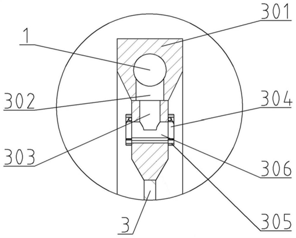
[0031] like Figure 1-6 As shown, the overall structural schematic diagram of the deep cavity filter plate combined filter press of the present invention is provided, and the shown deep cavity filter plate combined filter press includes a box type filter plate 3, a membrane filter Plate 5 and PLC automatic control system, and a sealed filter chamber 6 is formed between adjacent box filter plates 3 and diaphragm filter plates 5 . The upper and lower ends of the box-type filter plate 3 are respectively provided with a feed pipe 1 and an outlet pipe 9, the lower end of the feed pipe 1 is provided with a discharge port 2, the discharge port 2 communicates with the inner cavity of the filter chamber 6, and the discharge pipe 9 The upper end of the upper end is provided with a water inlet for filtered water infiltration, and the water inlet communicates with...


PUM


Abstract

A deep-cavity filter plate combined filter press provided by the invention comprises a box type filter plate, a diaphragm filter plate and a PLC automatic control system. A sealed filter chamber is formed between the adjacent box type filter plate and diaphragm filter plate. The deep-cavity filter plate combined filter press is characterized in that a feeding pipeline and a water outlet pipeline are arranged at the upper end and the lower end of the box type filter plate respectively, a pressure sensor is arranged in the filter chamber, and the pressure sensor is connected with the PLC automatic control system and is used for automatically monitoring the pressure change in the filter chamber; automatic control valves are arranged on a feeding pipe connected with the feeding pipeline, a water outlet pipe connected with the water outlet pipeline and a water inlet pipe connected with a water inlet pipeline; and the box type filter plate and the diaphragm filter plate are respectively provided with traction mechanisms, the traction mechanisms are controlled by a hydraulic oil cylinder to provide advancing power, and the hydraulic oil cylinder is connected with the PLC automatic control system. The overall filter pressing efficiency of the filter press is improved, the thickness of a filter cake is increased, and the maximum filter pressing thickness reaches 60 mm.

Description

technical field [0001] The invention relates to the field of filter presses, in particular to a filter press with combined deep-cavity filter plates. Background technique [0002] The working pressure of the traditional filter press is low, and the filter cake is not completely pressed. The pressed filter cake must go through drying and other processes before it can reach the use standard. For the subsequent transportation and treatment, it will greatly increase the cost of the enterprise. Big business burden. [0003] Moreover, during the filter press process, material blockage often occurs in the feed of the filter press, insufficient feed or excessive feed overflows between the filter press filter plates, resulting in damage to the filter plate, which is difficult to control, and the damaged parts cannot be found in time, resulting in Faults such as filter plate damage and material blockage often occur when the filter press is used, and maintenance is difficult, resultin...

Claims


Application Information

Patent Timeline
IPC IPC(8): B01D25/12B01D25/30
CPCB01D25/007B01D25/30
Inventor 沈玺
Owner 山东菲特环保设备有限公司
Learn More