Ultrafine grinding device for high-temperature-resistant pigment for pavements
A high temperature resistant pigment and ultra-fine grinding technology, applied in the field of pigment production, can solve the problems of general grinding efficiency and inability to classify grinding, and achieve the effects of improving grinding efficiency, convenient operation and preventing deflection.
- Summary
- Abstract
- Description
- Claims
- Application Information
AI Technical Summary
Problems solved by technology
Method used
Image
Examples
Embodiment 1
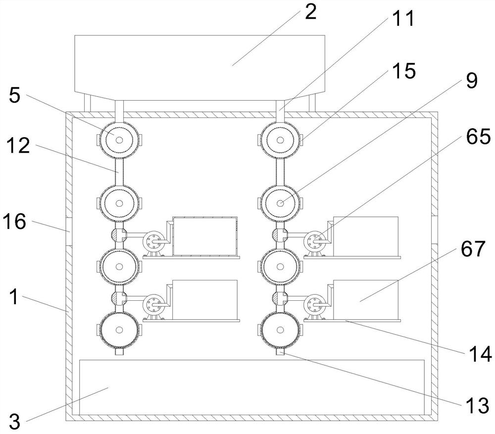
[0030] In this embodiment, as shown in Figures 1-5, a high-temperature-resistant pigment ultra-fine grinding device for road surfaces includes a box body 1, the box body 1 is provided with a side door, and a storage hopper 2 is fixed on the top of the box body 1, and There are multiple groups of grinding parts inside the box body 1, and the multiple groups of grinding parts are connected to the storage hopper 2 correspondingly, and the bottom wall of the box body 1 is provided with a receiving box 3;
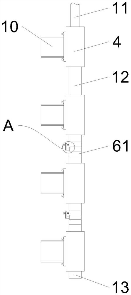
[0031] Grinding parts include a plurality of grinding shells 4 vertically fixed on the inner wall of the casing 1, a strut 15 is also arranged between the grinding shells 4 and the inner wall of the casing 1, and the rear end of the strut 15 is connected to the rear wall of the casing 1. fixed, and the inner end of the pole 15 is fixed to the outer end of the grinding shell 4. A plurality of grinding shells 4 are provided with grinding blocks 5, and the diameters of the pluralit...
Embodiment 2
[0033] On the basis of Embodiment 1, the outer end of the box body 1 is provided with a vent 16, and the two connecting pipes 12 on the lower side are provided with a retrieving mechanism 6. The circular shell 61 is provided with a rotating block 63 inside the circular shell 61. The rotating block 63 is provided with a channel 1 64 along the vertical direction, and the position of the rotating block 63 corresponding to the inner wall of the channel 1 64 is provided with a channel 2 69 along the horizontal direction. One end of shell 61 away from channel 2 69 is provided with a through hole 62, and the position of circular shell 61 corresponding to channel 2 69 is connected with suction fan 65, and the other end of suction fan 65 is connected with feeding pipe 66, and the other end of feeding pipe 66 A collection box 67 is connected to it, and a filter screen 68 is penetrated and fixed on a side wall of the collection box 67 away from the suction fan 65 . The rear end of the ro...
Embodiment 3
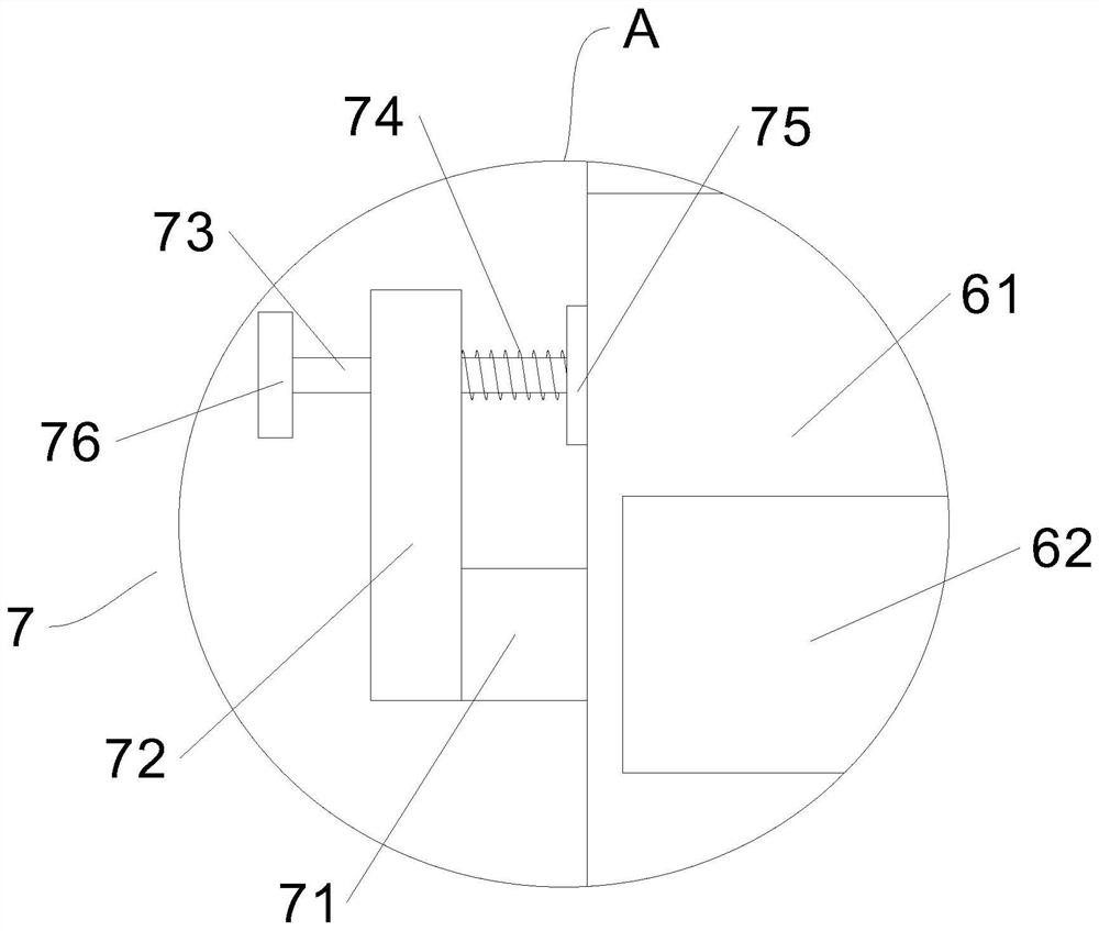
[0036] On the basis of Embodiment 2, the locking mechanism 7 includes a connecting rod 72 fixed to the extended end of the rotating rod 71, the connecting rod 72 is slidably connected with a front and rear support rod 73, and the rear end of the support rod 73 is fixed with a handle 76. , and the front end of the support rod 73 is fixed with a pressing plate 75 , and the supporting rod 73 is sleeved and fixed with a spring 74 corresponding to the position between the connecting rod 72 and the pressing plate 75 . A friction pad is fixed on the front end of the pressing plate 75 . Through the above method, the handle 76 is pulled backward, the pressing plate 75 is separated from the round shell 61, and then the connecting rod 72 is rotated to drive the rotating rod 71 and the rotating block 63 to rotate. After the rotation is completed, the handle 76 is released, Under the elastic force of the spring 74, the pressing plate 75 is pressed against the circular shell 61, effectively...
PUM
 Abstract
Description
Claims
Application Information
 - R&D
- Intellectual Property
- Life Sciences
- Materials
- Tech Scout
- Unparalleled Data Quality
- Higher Quality Content
- 60% Fewer Hallucinations
Browse by: Latest US Patents, China's latest patents, Technical Efficacy Thesaurus, Application Domain, Technology Topic, Popular Technical Reports.
© 2025 PatSnap. All rights reserved.Legal|Privacy policy|Modern Slavery Act Transparency Statement|Sitemap|About US| Contact US: help@patsnap.com


