Grinding flow-guiding device suitable for grinding high-injection-pressure injection nozzle needle valve and grinding method

A diversion device and injection pressure technology, which is applied in the direction of abrasive material feeding device, abrasive material, metal processing equipment, etc., can solve the problems such as uncontrollable rounded corner shape of nozzle hole entrance, high processing pressure time, extrusion deformation of nozzle hole, etc. , to achieve the effect of prolonging the grinding time, prolonging the service life and reducing the flow loss

Active Publication Date: 2017-06-13
CHINA FIRST AUTOMOBILE
View PDF7 Cites 1 Cited by
  • Summary
  • Abstract
  • Description
  • Claims
  • Application Information

AI Technical Summary

Problems solved by technology

The main methods known to increase the amount of grinding include increasing the processing pressure and prolonging the processing time. However, the conventional extrusion grinding process is limited by the domestic processing equipment and level. If the processing pressure is too high or the time is too long, it is easy to cause extrusion deformation of the nozzle hole. , the highest flow coefficient can only reach about 0.8
On the other hand, at present, it is mainly judged whether the extrusion grinding is qualified by detecting the flow coefficient of the needle valve body, and the shape of the extrusion hole entrance fillet cannot be controlled.

Method used


Image

  • Grinding flow-guiding device suitable for grinding high-injection-pressure injection nozzle needle valve and grinding method
  • Grinding flow-guiding device suitable for grinding high-injection-pressure injection nozzle needle valve and grinding method
  • Grinding flow-guiding device suitable for grinding high-injection-pressure injection nozzle needle valve and grinding method

Examples


Embodiment Construction

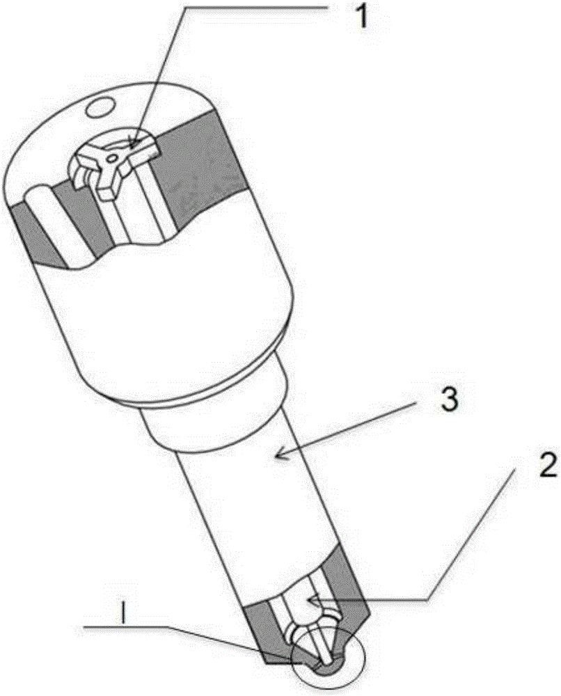
[0024] like image 3 , 4 Shown is a grinding guide device suitable for grinding the needle valve body of a high injection pressure fuel injection nozzle, including a positioning pin 1 and a guide rod 2 connected with the positioning pin 1; the positioning pin 1 is arranged on the needle valve of the fuel injection nozzle The movement of the guide rod 2 is restricted in the cavity of the body 3, and the head of the guide rod 2 is located at the entrance of the spray hole of the needle valve body 3 of the fuel injector, covering the lower half of the fillet of the spray hole entrance. The guide rod 2 is stepped, and the diameter of the head is smaller than the diameter of the tail. The head of the guide rod 2 is a plane, which is compatible with the size of the head of the needle valve body 3 of the fuel injector. The positioning pin 1 is a trident structure, and its diameter is adapted to the diameter of the cavity at the tail of the needle valve body 3 of the fuel injector. ...


PUM


Abstract

The invention discloses a grinding flow-guiding device suitable for grinding a high-injection-pressure injection nozzle needle valve. The grinding flow-guiding device comprises a locating pin and a flow guiding rod connected with the locating pin. The locating pin is arranged in a cavity of the injection nozzle needle valve to limit movement of the flow guiding rod, and the head of the flow guiding rod is located at an injection hole inlet of the injection nozzle needle valve to shield the circular bead on the lower half part of the injection hole inlet. A grinding method includes the steps of primary conventional grinding, secondary grinding conducted after installation of the grinding flow-guiding device, and re-grinding conducted after removal of the grinding flow-guiding device. According to the injection nozzle needle valve ground by the grinding flow-guiding device through the grinding method, at the aspect of injection nozzle performance, flow loss in an injection nozzle is further reduced, the flow coefficient is remarkably increased, the probability of cavitation erosion of an injection hole under high injection pressure is lowered, and the service life of the injection nozzle under the high injection pressure is prolonged. At the aspect of a process, the grinding time of the needle valve is prolonged, and the situation that according to a conventional grinding method, with increasing of the grinding time, the overall grinding degree of the injection hole inlet of the needle valve is improved, and interference between the injection holes occurs too early is avoided.

Description

technical field [0001] The invention belongs to the technical field of fuel injector processing, in particular to a grinding guide device suitable for grinding a needle valve body of a high injection pressure fuel injection nozzle. Background technique [0002] At present, the common principle of liquid extrusion grinding of needle valve body is as follows: Image 6 shown. The needle valve body is clamped by the clamping cylinder, and the high-pressure abrasive enters the middle hole of the processed fuel injection nozzle from the clamp, and returns to the collection box through the pressure chamber and the spray hole. Under the action of high pressure, the abrasive generates a certain pressure and cutting abrasive flow on the nozzle hole and pressure chamber of the fuel injector, thereby micro-grinding the pressure chamber of the needle valve body, the corner burrs and the surface of the nozzle hole. Through grinding, a rounded corner of a certain size is formed in the tra...

Claims


Application Information

Patent Timeline
Patent Type & Authority Applications(China)
IPC IPC(8): B24C7/00
CPCB24C7/00
Inventor 吴月杨海涛陈大陆钟博李建珍张清林李海洋周德广
Owner CHINA FIRST AUTOMOBILE
Why Eureka
Try Eureka