A high-efficiency cutting blade

A cutting insert and high-efficiency technology, used in milling cutters, metal processing equipment, milling machine equipment, etc., can solve the problems of rapid damage of the main cutting edge, large cutting allowance of the blade, abnormal wear of the blade edge, etc., to ensure the surface quality. , Improve the durability, protect the effect of the wiper

Active Publication Date: 2022-06-03
ZHUZHOU HUARUI PRECISION CUTTINGS TOOLS CO LTD
View PDF7 Cites 0 Cited by
  • Summary
  • Abstract
  • Description
  • Claims
  • Application Information

AI Technical Summary

Problems solved by technology

[0005] However, especially under high-feed cutting conditions where the feed rate per tooth is about 0.8 to 1.0mm / tooth, larger iron filings will be formed. The thicker the iron filings, the greater the cutting resistance the tool must bear. The larger the cutting resistance is, the main cutting resistance acts on the main cutting edge, and a large amount of cutting heat is generated. There is a high probability that the cutting edge of the blade will experience abnormal wear, and even chipping, which will affect the service life of the blade. In high-efficiency machining with high quality requirements, it is particularly important to reduce the cutting resistance impact of the main cutting edge, especially the wiper edge. Generally, in high-speed feed processing, the cutting allowance of the blade is large, and the cutting resistance and cutting heat It will completely act around the main cutting edge, resulting in faster damage to the main cutting edge, and the surface quality of the part cannot be guaranteed

Method used


Image

  • A high-efficiency cutting blade
  • A high-efficiency cutting blade
  • A high-efficiency cutting blade

Examples


Embodiment 1

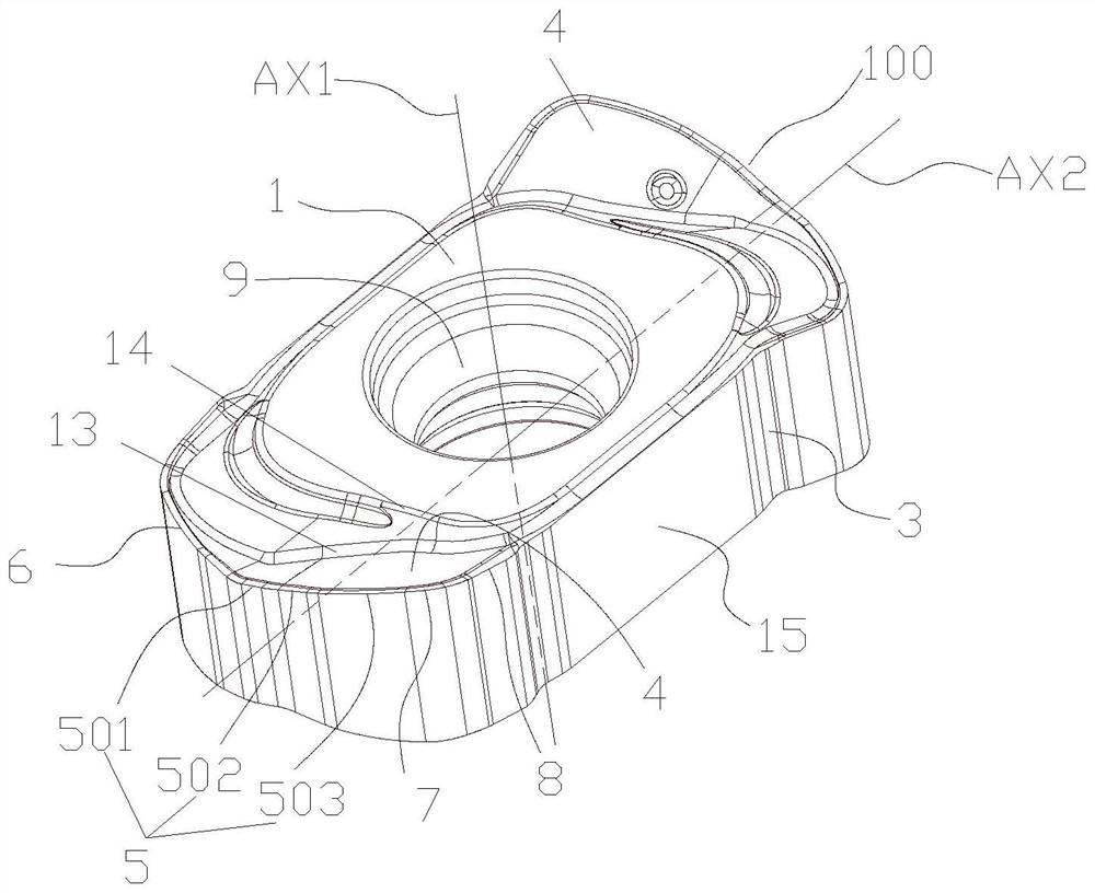
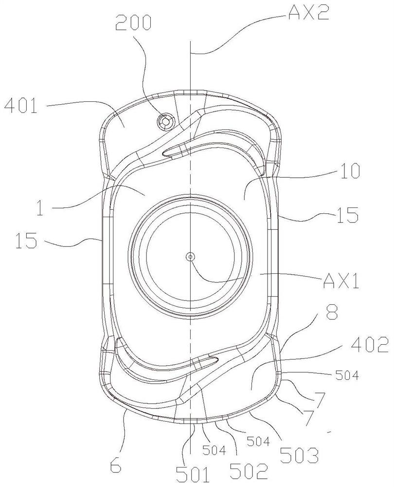
[0041] like figure 1 Shown is a high-efficiency cutting insert described in this embodiment, including an insert body 100 surrounded by an upper bottom surface 1, a lower bottom surface 2, and a side surface 3 connecting the upper bottom surface 1 and the lower bottom surface 2, the insert The cutting unit 4 is distributed on the main body 100, and the cutting unit 4 includes at least one main cutting edge 5. Under the cutting condition of a certain feed amount, the blade main body 100 and the part move relative to the main cutting edge 5 to promote the blade main body. 100 cuts into the interior of the part, forms curled chips on the rake face, and removes excess material; the main cutting edge 5 is composed of a wiper edge 501, a first cutting edge 502 and a second cutting edge 503. The wiper edge 501 is in a straight state, the wiper edge 501, the first cutting edge 502 and the second cutting edge 503 protrude toward the outer direction of the insert body 100 and form a spa...

Embodiment 2

[0061] like Figure 12 As shown, this embodiment differs from Embodiment 1 in the way of assembling the blade body 100 . Specifically, the blade body 100 can be rotated counterclockwise around the rotation center 28 for cutting processing, which widens the blade body 100 The use range of the blade body 100 enables all parts of the blade body 100 to function. The blade main body 100 is also installed on the blade body with a negative axial angle for cutting, and the cutting clearance angle is reserved. For the polishing effect of the surface of the part, the second secondary cutting edge undertakes the main work of removing the material of the part. At the same time, the secondary cutting edge and its secondary emptying edge will also participate in the actual cutting task in the case of a large depth of cut. At the same time, the secondary cutting edge 6 The first secondary cutting edge, the second secondary cutting edge and their bridging curves are all convex and curved tow...


PUM


Abstract

The invention discloses a high-efficiency cutting blade, which includes a blade body surrounded by an upper bottom surface, a lower bottom surface, and a side surface connecting the upper bottom surface and the lower bottom surface. Cutting units are distributed on the blade body, and the cutting unit includes At least one main cutting edge, the main cutting edge is composed of a wiper edge, a first cutting edge and a second cutting edge, the wiper edge is in a straight line, between the wiper edge and the first cutting edge, the second The first cutting edge and the second cutting edge are smoothly connected by first bridging curves respectively. The invention can realize the decomposition of cutting resistance, reduce the impact of cutting resistance on the wiper blade, reduce the damage probability of the wiper blade, and continuously and stably process high-quality surfaces while ensuring efficient cutting.

Description

technical field [0001] The invention relates to the technical field of metal cutting, in particular to a high-efficiency cutting insert. Background technique [0002] In metal cutting, milling is the most common processing method. Usually, the parts to be processed are fixed on the machine tool console, and a high-speed rotating milling tool is used to move the surface of the parts at a certain feed rate, and the processing is done. The shape and characteristics of the part are required, and the feed of the tool determines the cutting efficiency of the tool. If the feed per tooth (or per revolution) of the tool is larger, the volume of iron filings removed will be larger, which means that the total mass of iron filings processed per unit time is greater, which can be understood as the The higher the metal removal rate, the higher the cutting efficiency of the insert. In order to improve the metal removal rate and pursue high cutting efficiency, in the structural design of ...

Claims


Application Information

Patent Timeline
Patent Type & Authority Patents(China)
IPC IPC(8): B23C5/02B23C5/28
CPCB23C5/28B23C5/02
Inventor 陈胜男刘承军吴志龙肖旭凯高江雄
Owner ZHUZHOU HUARUI PRECISION CUTTINGS TOOLS CO LTD
Why Eureka
Try Eureka