Discharging mechanical arm of mechanical hand device

A mechanical arm and manipulator technology, applied in the field of robotics, can solve the problems of time-consuming and laborious, high labor cost, and hidden safety hazards of manual handling.

Inactive Publication Date: 2021-11-16
康凤林
View PDF0 Cites 4 Cited by
  • Summary
  • Abstract
  • Description
  • Claims
  • Application Information

AI Technical Summary

Problems solved by technology

[0003] The present invention provides a feeding mechanical arm of a manipulator device to solve the problems 1. Currently, manual transfer or handling is generally used, which has high labor costs, time-consuming and laborious, and is not conducive to the improvement of pro...

Method used


Image

  • Discharging mechanical arm of mechanical hand device
  • Discharging mechanical arm of mechanical hand device
  • Discharging mechanical arm of mechanical hand device

Examples


Embodiment 1

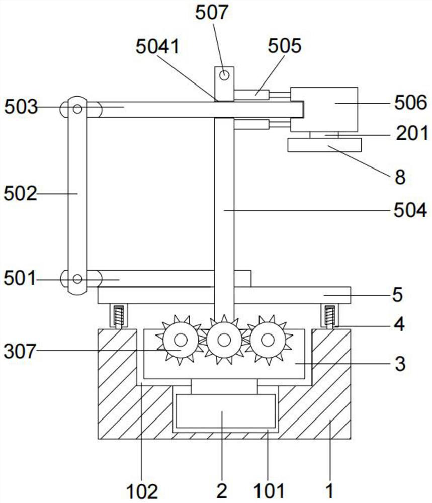
[0037] The embodiment of the present invention provides a kind of unloading robot arm of manipulator device, such as figure 1 As shown, the power base 1 is included, and the left and right sides of the upper end of the power base 1 are symmetrically provided with a shock absorbing mechanism 4, and the middle part of the upper end of the power base 1 is provided with an adjustment cavity 102, and the shock absorbing mechanism 4 is connected with a mechanical arm mechanism. The mechanical arm mechanism includes a guiding mechanism and a clamping mechanism 8, the guiding mechanism is connected with the clamping mechanism 8 through a motor two 201, and an angle adjusting mechanism is arranged inside the adjustment chamber 102, and the angle adjusting mechanism is connected with a guide Mechanism, the electrical components in the power base 1, the mechanical arm mechanism, the clamping mechanism 8 and the angle adjustment mechanism are connected with a control part, and the control ...

Embodiment 2

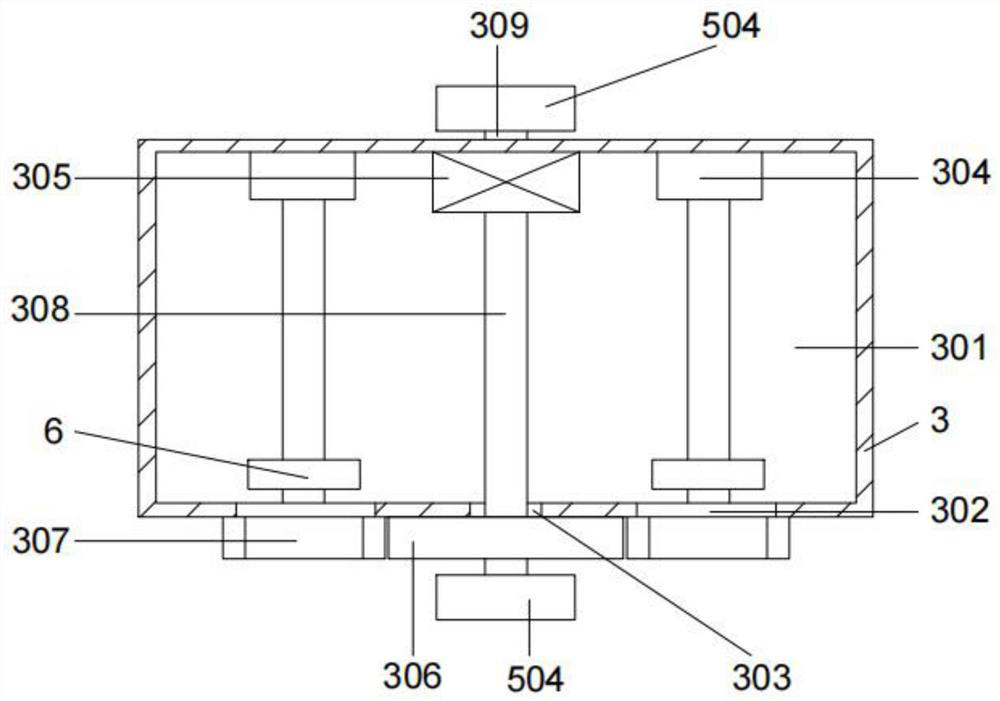
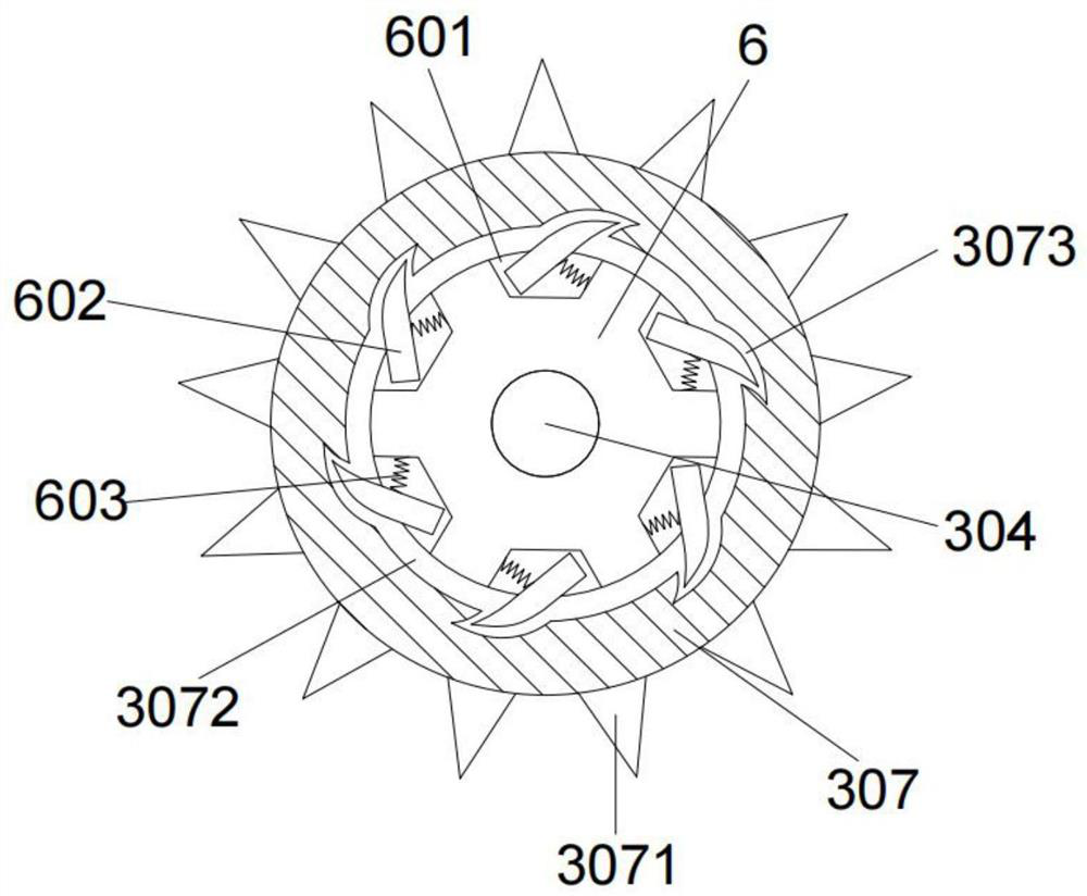
[0041] On the basis of above-mentioned embodiment 1, as Figure 2-Figure 3 As shown, the angle adjustment mechanism includes a working shell 3, the inside of the working shell 3 is provided with a working chamber 2 301, and the left and right sides of the front end of the working shell 3 are provided with an opening 302. The middle part of the front end is provided with an opening 2 303, and the opening 302 communicates with the working chamber 2 301. The left and right sides of the rear end of the working chamber 2 301 are symmetrically provided with an electric telescopic rod 1 304, and the electric telescopic rod 1 304 The front end is fixedly connected with an adjustment balance mechanism, and the middle part of the rear end of the working chamber 2 301 is fixedly provided with a motor 3 305, and the motor 3 305 is fixedly connected with a fixed shaft 308, and the fixed shaft 308 passes through the opening 2 303 is fixedly connected with gear 1 306, and the left and right ...

Embodiment 3

[0046] On the basis of Example 2, such as figure 1 , Figure 4 As shown, the inside of the power base 1 is provided with a working chamber 101, and the working chamber 101 communicates with the adjustment chamber 102 up and down, and the inside of the working chamber 101 is fixed with a motor 2. The fixedly connected motor shaft is fixedly connected with the working shell 3 in the angle adjustment mechanism.

[0047] The shock absorbing mechanism 4 includes a shock absorbing shell 401, which is slidably connected with the guide mechanism. The shock absorbing shell 401 is provided with a buffer cavity 402 inside, and the lower end of the shock absorbing shell 401 is provided with a Opening 3 403, the inside of the buffer chamber 402 is slidingly provided with a buffer plate 404, the buffer plate 404 is fixedly connected with the buffer block 406, the buffer block 406 is sleeved with a spring 2 405 and the spring 2 405 is fixed on the buffer plate Between 404 and the buffer ch...


PUM


Abstract

The invention provides a discharging mechanical arm of a mechanical hand device. The discharging mechanical arm comprises a power base. Shock absorption mechanisms are symmetrically arranged on the left side and the right side of the upper end of the power base, an adjusting cavity is formed in the middle of the upper end of the power base, the shock absorption mechanisms are connected with a mechanical arm mechanism, and the mechanical arm mechanism comprises a guide mechanism and a clamping mechanism. The guide mechanism is connected with the clamping mechanism through a second motor, an angle adjusting mechanism is rotationally arranged inside the adjusting cavity and connected with the guide mechanism, and electric devices in the power base, the mechanical arm mechanism, the clamping mechanism and the angle adjusting mechanism are connected with a control piece. The discharging mechanical arm solves at least one of the problems that firstly, manual transfer or carrying operation is generally adopted at present, the labor cost is high, time and labor are wasted, the improvement of the production efficiency is not facilitated, and potential safety hazards exist in manual carrying; and secondly, when a mechanical arm transports an object, if the weight of the object is too large, the transportation process of the mechanical arm is unstable.

Description

technical field [0001] The invention relates to the technical field of robots, in particular to a feeding robot arm of a robot device. Background technique [0002] The robotic arm is the most widely used automatic mechanical device in the field of robot technology. Now in the process of product processing in the engineering industry, construction industry, chemical industry, etc., its products need to go through multiple processes to complete the process, and the previous process to the next When processing between one process, it is often necessary to complete the transfer or handling of the product to be formed. Currently, manual transfer or handling is generally used, which has high labor costs, time-consuming and laborious, and is not conducive to the improvement of production efficiency. At the same time, manual handling has potential safety hazards; and When the robot arm transports items, if the item is too heavy, the transport process of the robot arm is unstable. ...

Claims


Application Information

Patent Timeline
IPC IPC(8): B25J9/12B25J15/00B25J15/02B25J19/00
CPCB25J9/12B25J9/102B25J9/109B25J15/0052B25J15/0206B25J19/0091
Inventor 康凤林
Owner 康凤林
Why Eureka
Try Eureka