Production equipment for flat lifting belt

A technology for production equipment and hoisting belts, applied in the direction of measuring devices, textile material processing, textiles and papermaking, etc., can solve the problems of too many correction devices and the inability to monitor equipment in real time, so as to ensure position stability and level uniformity in real time The effect of monitoring

Inactive Publication Date: 2021-11-16
泰州市力夫特绳网带厂
View PDF1 Cites 3 Cited by
  • Summary
  • Abstract
  • Description
  • Claims
  • Application Information

AI Technical Summary

Problems solved by technology

[0003] In the prior art, there are also some technical solutions about the adjustment of the dyeing roller of the hoisting belt. For example, a Chinese patent with the application number CN111618100A discloses a roll positioning adjustment mechanism, which includes a fixed plate and two rolls. The upper surface of the fixed plate is There are through holes at the four corners, the outer wall of the fixing bolt is movably connected with the adjustment assembly, the opposite side of the two sliders is fixedly connected with the moving block, and the upper surface of the moving block is fixedly connected with the L-shaped plate; the roller positioning The adjustment mechanism makes the maintenance process of the bottom rolls of the rolling mill convenient and labor-saving, improves the convenience and efficiency of the maintenance of the bottom rolls, and can also effectively improve the convenience and efficiency of the installation and positioning adjustment of the rolls, and at the same time reduce the work difficulty of the staff. However, this equipment Real-time monitoring is impossible, because the roll deflection range is not the same every time, it needs to be adjusted to different degrees, and there are many requirements for the calibration device, which cannot meet these requirements

Method used


Image

  • Production equipment for flat lifting belt
  • Production equipment for flat lifting belt
  • Production equipment for flat lifting belt

Examples


Embodiment 1

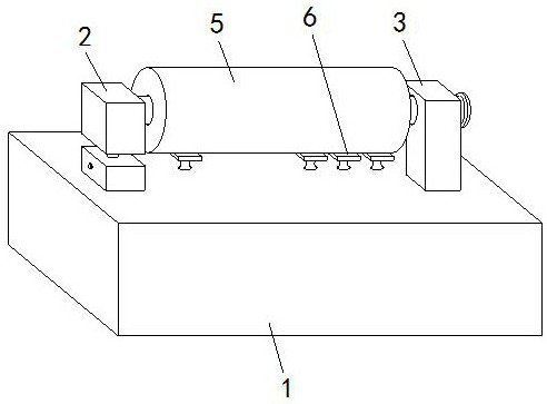
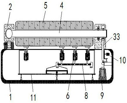
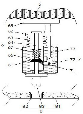
[0034] Such as Figure 1 to Figure 5 As shown, the production equipment of the flat lifting belt according to the present invention includes a workbench 1, on which a roll 5 is installed through a rotating shaft 4, and the inside of the workbench 1 and below the roll 5 are evenly distributed Driven assembly 6, the inside of workbench 1 and below driven assembly 6 are equipped with sensing assembly 8; during work, when roll 5 deflects, it will drive driven assembly 6 below it to move and communicate with sensing assembly 8 Contact, because the roll 5 is skewed, therefore, the amplitude of the driven assembly 6 at different positions being squeezed by the roll 5 is inconsistent, by counting the number of driven assemblies 6 that are in contact with the sensing assembly 8, you can The degree of deflection of the roll 5 is judged.

[0035] Two main mounts 2 are installed on the workbench 1, a rotating shaft 4 is installed between the two main mounts 2, and a roll 5 is installed o...

Embodiment 2

[0045] Such as Figure 6-7As shown in Comparative Example 1, another embodiment of the present invention is: the main mounting base 2 is provided with a positioning assembly 3, and the positioning assembly 3 includes a secondary bearing 31 and a main bearing 32 installed on the rotating shaft 4, A support spring set is installed on the secondary bearing 31, and a strut 33 is movably clamped under the main bearing 32, and the strut 33 is movably inserted into the inside of the workbench 1; when working, the right end of the rotating shaft 4 is installed on the main mounting seat through the bearing 2, as shown in Embodiment 1, the right end of the rotating shaft 4 is supported by the main bearing 32, the main bearing 32 is installed on the strut 33, and the strut 33 is fixed by the elastic rod 102 at the same time, therefore, the right end of the rotating shaft 4 is Installed on the support rod 33 with a fixed position, the two bearings play a double support role for the rotati...


PUM


Abstract

The invention belongs to the field of lifting belt production, and particularly relates to production equipment for a flat lifting belt. The equipment comprises a workbench; a roller is installed on the workbench through a rotating shaft; driven assemblies which are evenly distributed are installed in the workbench and located below the roller; a sensing assembly is installed in the workbench and located below the driven assemblies; a clutch assembly is installed above a correction assembly; and a horizontal assembly is installed below the sensing assembly. After the roller deflects, a T-shaped pipe drives a transverse plate to deflect, a rolling ball rolls and touches a switch key, a circuit of a circuit board is connected, an electromagnet is electrified to have magnetism and repels a magnetic block in the same polarity, a rack plate is pushed to move upwards, the rack plate drives a cam to rotate through a gear, the cam rotates to extrude a supporting rod to move upwards, and then the right end of the roller is driven to move upwards, so that the function of correcting the roller is achieved.

Description

technical field [0001] The invention belongs to the field of sling production, in particular to a production equipment for flat slings. Background technique [0002] In the process of production and construction, there are often lifting operations, which require the use of flat slings. When producing flat slings, the raw materials are first inspected. After passing the inspection, they enter the process of webbing, dyeing, and word lifting. After warping, the The filaments are processed into warp beams that meet the weaving requirements, put on the loom ribbon, and put the belt skin into the dyeing tank for dyeing. The coloring is different for different lifting weights. Use 40°C to adjust the dyeing solution. The temperature should not be too high, otherwise it will be easy to coagulate. The amount of dyeing solution in the rolling tank should not be too much, and it can be added as it is used. Pay attention to the uniformity of the rolls during padding. The existing adjust...

Claims


Application Information

Patent Timeline
Patent Type & Authority Applications(China)
IPC IPC(8): D06B3/18G01C9/00G01C9/02
CPCD06B3/18G01C9/00G01C9/02
Inventor 徐春忠
Owner 泰州市力夫特绳网带厂
Why Eureka
Try Eureka