
Fence and fence barrier gate

A fence and gate technology, applied in the field of access control equipment, can solve the problems of fences occupying space, inconvenient to carry, easy to damage, etc., to achieve the effects of easy handling and transportation, reduced transportation costs, and convenient operation.

Pending Publication Date: 2021-11-16
GUANGDONG ANKUAI INTELLIGENT TECH CO LTD
View PDF0 Cites 0 Cited by
  • Summary
  • Abstract
  • Description
  • Claims
  • Application Information

AI Technical Summary

Problems solved by technology

At present, when the fence is transported and packed, due to the long main pole, the whole fence takes up a lot of space, which is inconvenient to transport. The overall fence is relatively heavy, inconvenient to carry, and easy to damage

Method used


Image

  • Fence and fence barrier gate
  • Fence and fence barrier gate
  • Fence and fence barrier gate

Examples


Embodiment 1

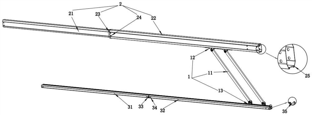
[0036] see figure 1 , a fence, the fence includes a main rod assembly 2, a secondary rod assembly 3 and a plurality of vertical rod assemblies 1, and a plurality of vertical rod assemblies 1 are arranged between the main rod assembly 2 and the secondary rod assembly 3;

[0037] The main rod assembly 2 includes an inner main rod 21 and an outer main rod 22, the inner main rod 21 is arranged in the outer main rod 22, the inner main rod 21 slides relative to the outer main rod 22, and part of the length of the inner main rod 21 protrudes from the outer main rod 22 Thereby changing the length of the main rod assembly 2.

[0038] The inner main pole 21 can be telescopically accommodated in the outer main pole 22, which reduces the length of the main pole and reduces the space occupied by the fence. In addition, it is convenient for handling and transportation, and effectively reduces transportation costs.

[0039] In an optional embodiment, the sub-rod assembly 3 includes an inner...

Embodiment 2

[0053] see Figure 2-3 , a barricade, the barricade includes a host 5 and the barrier structure described in Embodiment 1, the host 5 includes a driving mechanism, and the barrier structure is connected to the output end of the driving mechanism.

[0054] In an optional embodiment, the barrier gate further includes a column 4, which is arranged on the side of the fence structure away from the host 5, and the two ends of the column 4 are respectively connected to the main rod 2 and the auxiliary rod 3 in rotation. In order for the fence structure to have a better shock absorption effect with the ground when the gate is lowered, an elastic support foot 41 is provided at the end of the column 4 close to the ground.

[0055] Compared with the structure in the prior art where the main rod assembly 2 and the auxiliary rod assembly 3 are arranged on the side of the vertical rod assembly 1 close to the main machine 5, the orientation of the vertical rod assembly 1 needs to be distingu...


PUM


Abstract

The invention relates to the technical field of access control equipment, in particular to a fence and a fence barrier gate. The fence comprises a main rod assembly, an auxiliary rod assembly and a plurality of vertical rod assemblies, and the vertical rod assemblies are arranged between the main rod assembly and the auxiliary rod assembly. The main rod assembly comprises an inner main rod and an outer main rod, the inner main rod is arranged in the outer main rod, and the inner main rod slides relative to the outer main rod to change the length of the main rod assembly. The inner main rod is telescopically contained in the outer main rod, when the fence is transported, the inner main rod is contracted into the outer main rod, the length of the main rod assembly is obviously reduced, the whole fence occupies a small space, carrying and transportation are convenient, and the transportation cost is effectively reduced. When the fence is used, the inner main rod is pulled out of the outer main rod and extends to the preset length, and operation is convenient.

Description

technical field [0001] The invention relates to the technical field of access control equipment, in particular to a fence and a fence gate. Background technique [0002] At present, there are many gate control agencies on the market, which are used in residential areas, parking lots, etc. Barrier gate, also known as car stopper, was originally introduced from abroad. Its English name is Barrier Gate. It is a channel entrance and exit management device specially used to restrict motor vehicles on the road. To manage the entry and exit of vehicles. The electric barrier gate can realize the landing bar through the wireless remote control alone, and can also implement the automatic management state through the parking lot management system (ie, the IC card management system). When entering the venue, the card is taken to release the vehicle. When leaving the venue, the parking fee is charged and the vehicle is automatically released. [0003] Barrier gates include fences, whic...

Claims


Application Information

Patent Timeline
IPC IPC(8): E01F13/06
CPCE01F13/06
Inventor 肖勇善刘训武陈国彬
Owner GUANGDONG ANKUAI INTELLIGENT TECH CO LTD
Learn More