

Virtual observer-based switching system quantization coding control method
A switching system and quantization coding technology, applied in the field of quantization coding and control of switching system based on virtual observer, can solve the problems of lack of effective coding transmission technology, modal mismatch, reducing quantizer design conservatism in switching system, etc. Achieve time consistency, reduce variance, and reduce conservatism
- Summary
- Abstract
- Description
- Claims
- Application Information
AI Technical Summary
Problems solved by technology
Method used
Image



Examples
Embodiment 1
[0062] An embodiment of the present invention provides a virtual observer-based switching system quantization coding control method, including:
[0063] Step S101: Design a virtual observer and a real observer by using the modal information and quantized values at the sampling time of the switching system received at the delay time;
[0064] Step S102: Design the quantization encoding rule at the sampling time based on the difference information of the delay time state and the real observer, and design a piecewise continuous controller based on the delay time to ensure the stable operation of the system.
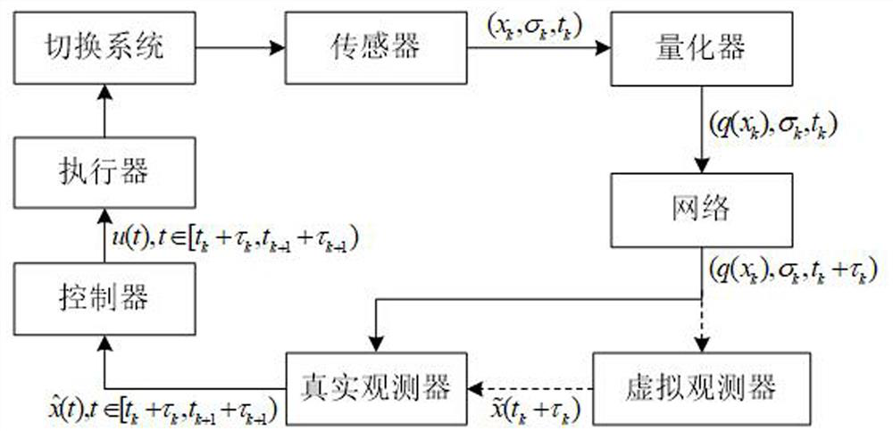
[0065] Specifically, the coding and control structure is as figure 1 As shown, the coding and control design process is as follows figure 2 shown, including the following steps:
[0066] Step A1: Design initial quantization rules, the design process is as follows image 3 shown;
[0067] Step A2: Collect modal information and status information of the switching system...
Embodiment approach
[0077] Taking the double-capacity water tank test bench as an example, the physical object of the test bench, the sensors and actuators adopted are as follows: Figure 5 As shown, the abstract structure is as Image 6 shown. In this system fluid flows through two tanks. The status value is the reservoir level (relative to its nominal value - dotted line). The flow between two vessels is proportional to their level difference. We assume that both flow control and level measurement can be switched arbitrarily from the first tank (actuator 1 - sensor 1) to the second tank (actuator 2 - sensor 2). We assume that, if uncontrolled, the inflow and outflow flows are constant and equal to the nominal value. For this system, the state matrix obviously remains unchanged, while the input and output matrices can be switched. Then the corresponding plant model is a continuous-time switching system:
[0078]
[0079] y(t)=C i x(t)
[0080] in: C 1 =[0 1],C 2 =[1 0].
[0081] If...
Embodiment 3
[0083] A method for controlling quantization coding of a switching system based on a virtual observer, comprising the following steps:
[0084] Step 1: Introduce a virtual observer, and update the virtual observer by using the modal information and quantization value received at the sampling time of the switching system received at the delay time, and design and update the real observer by using the state of the virtual observer at the delay time, to Solve the modal mismatch problem caused by delay;
[0085] Step 2: Based on the difference information between the state observer at the delay time and the real observer at the delay time, design the quantization rule at the next sampling time, and design a segmented continuous controller based on the state observer at the delay time to ensure the stable operation of the system .
[0086] In the aforementioned virtual observer-based switching system quantization coding control method, the design process of the virtual observer an...
PUM
 Abstract
Description
Claims
Application Information