Spraying device for hub production

A technology of spraying device and wheel hub, which is applied in the direction of spraying device, liquid spraying device, and device for coating liquid on the surface, etc. It can solve the problems of low efficiency and action time difference, and achieve the effects of preventing vibration, improving efficiency, and high coincidence

Active Publication Date: 2021-11-19
永康市跃飞车轮有限公司
View PDF22 Cites 9 Cited by
  • Summary
  • Abstract
  • Description
  • Claims
  • Application Information

AI Technical Summary

Problems solved by technology

[0004] The above-mentioned patents have the following disadvantages: the pick-and-place and clamping of the wheel hub are completely independent actions, which leads to the need for the entire pick-and-place and clamping process to be carried out independently, and there will be a difference in action time when performed independently, resulting in low efficiency

Method used


Image

  • Spraying device for hub production
  • Spraying device for hub production
  • Spraying device for hub production

Examples


Embodiment 1

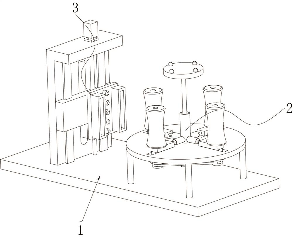
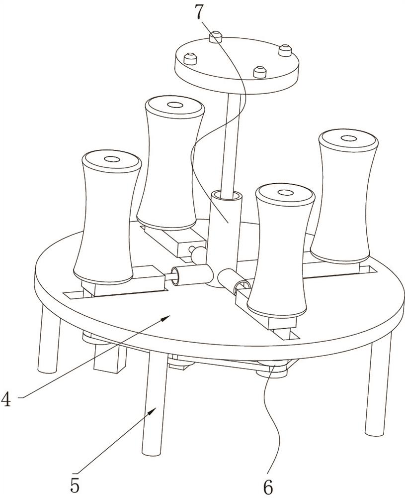
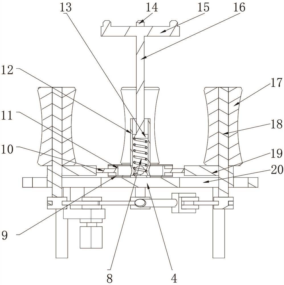
[0034] A spraying device for wheel hub production, such as Figure 1-3As shown, it includes a base 1 and a clamping drive mechanism 2 and a spraying mechanism 3 that are arranged on the top of the base 1 and cooperate with each other. The driving assembly 6 and the clamping assembly 7 on both sides of the support base 4 and cooperating with each other, the clamping assembly 7 includes a support plate 15 and a clamping curved roller assembly 17, and the bottom outer wall of the support plate 15 is rotatably connected with a connecting rod Two 16, the outer wall of the connecting rod two 16 is fixed with the piston two 13 by bolts, the outer wall of the piston two 13 cooperates to slide with the main cylinder body 12, and the outer wall of the main cylinder body 12 is welded with the branch cylinder body 9 communicating with its inner cavity, the branch cylinder The inner wall of the body 9 cooperates and slides with a piston-11, the outer wall of the piston-11 is fixed with a c...

Embodiment 2

[0039] A spraying device for wheel hub production, such as Figure 7 , 8 As shown, in order to solve the problem of cushioning and friction; this embodiment makes the following improvements on the basis of Embodiment 1: the clamping curved roller assembly 17 includes a roller body 40 and a buffer film 41 arranged on the outer wall of the roller body 40, The buffer film 41 includes two symmetrical side ribs 43 obliquely bonded to the outer wall of the roller body 40 and a support rib 42 bonded to the outer wall of the roller body 40, the support rib 42 is located on the axis of symmetry of the two side ribs 43 Location.

[0040] When this embodiment is in use, on the one hand, the arrangement of the support rib 42 and the side rib 43 can further buffer the collision between the roller body 40 and the hub to prevent damage; on the other hand, the support rib 42 and the side rib 43 Designed with a high triangular structure, when the clamping force is small, the shrinkage of the...

Embodiment 3

[0042] A spraying device for wheel hub production, such as Figure 7 , 8 As shown, in order to solve the spraying problem; the present embodiment makes the following improvements on the basis of embodiment 1 and embodiment 2: the spraying mechanism 3 includes an "L" type bracket 28 and a spray nozzle 32, and the "L" type bracket 28 is fixed on the top outer wall of the base 1 by bolts, and the outer wall of the "L"-shaped bracket 28 is slidably connected with a lifting plate 34 through a linear slide rail 35, and the outer wall of the lifting plate 34 is provided with an adjustment plate 31, and the spray nozzle 32 Be fixed on the outer wall of the adjusting plate 31 by bolts, and the spray nozzle 32 is connected to the outer wall spray pump; when the spray pump starts, the spray medium can be delivered to the spray nozzle 32, so that the medium is sprayed to the surface of the hub by the spray nozzle 32; Both sides of the symmetry of the spray nozzle 32 are provided with div...


PUM


Abstract

The invention discloses a spraying device for hub production, and relates to the technical field of hub spraying. The invention aims to solve the problems of synchronism and efficiency. The spraying device specifically comprises a base and a clamping driving mechanism and a spraying mechanism. The clamping driving mechanism and the spraying mechanism are arranged at the top of the base and matched with each other, and the clamping driving mechanism comprises a supporting seat fixed to the outer wall of the top of the base through supporting legs, a driving assembly and a clamping assembly, wherein the driving assembly and the clamping assembly are arranged on the two sides of the supporting seat and matched with each other. According to the spraying device for hub production, when a hub descends due to gravity, a downward pressing supporting disc descends, so that a second piston descends, the pressure in a cavity of a main cylinder body is increased, a first piston is ejected out, a first connecting rod drives an L-shaped sliding block and a clamping cambered surface roller assembly to slide towards the outer side, the inner ring wall of the hub is clamped and fixed, and when the hub is sprayed, the hub is lifted upwards. A first spring can bounce the second piston, so that the clamping cambered surface roller assembly is shrunk towards the inner side, synchronism of clamping and taking and placing is achieved, and the efficiency is improved.

Description

technical field [0001] The invention relates to the technical field of wheel hub spraying, in particular to a spraying device for wheel hub production. Background technique [0002] As an important part of the car, the wheel hub not only carries the weight of the car and the function of driving safety, but also has the function of beautifying the car body and showing individuality. With the increasing application of aluminum alloy wheels in automobiles, people's requirements for aluminum alloy wheels are also increasing, not only requiring high mechanical properties, but also requiring excellent appearance and corrosion resistance. Spraying treatment is usually carried out before. [0003] In the prior art, such as the Chinese patent with the publication number CN212791520U, a spraying device for an aluminum alloy wheel hub is disclosed, which includes a carrier plate, a power push rod is fixedly installed on the top of the carrier plate, and the output end of the power pus...

Claims


Application Information

Patent Timeline
Patent Type & Authority Applications(China)
IPC IPC(8): B05B13/02B05B9/04B05B16/20B05D3/04B08B5/02B05B15/68
CPCB05B13/0228B05B13/0278B05B9/0403B05B16/20B05D3/0413B08B5/023B05B15/68Y02P70/10
Inventor 章跃飞章平川
Owner 永康市跃飞车轮有限公司
Why Eureka
Try Eureka