
Boring machine with anti-passivation structure for machining

A technology of machining and tools, applied in the direction of manufacturing tools, metal processing equipment, metal processing mechanical parts, etc., can solve the problems of tool operation interference, easy passivation, etc., to reduce the service life, uniform force, increase resistance. Effect

Inactive Publication Date: 2021-11-19
东莞市达盛机电设计有限公司
View PDF0 Cites 0 Cited by
  • Summary
  • Abstract
  • Description
  • Claims
  • Application Information

AI Technical Summary

Problems solved by technology

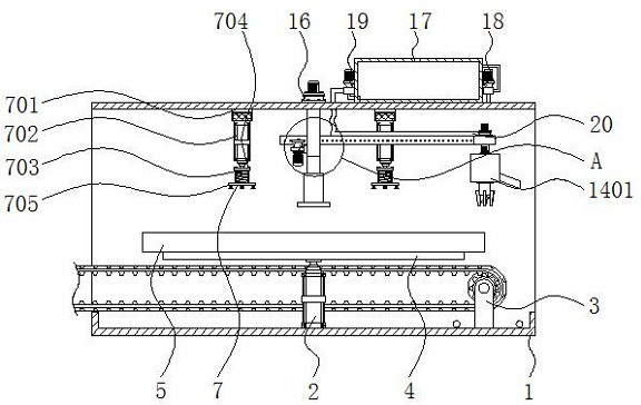
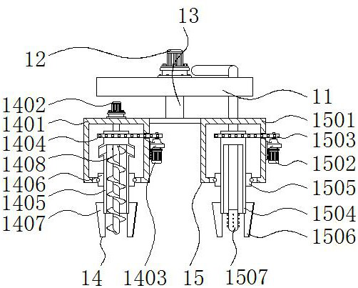
[0004] The purpose of the present invention is to provide a boring machine with an anti-passivation structure for mechanical processing, so as to solve the problem that the existing boring machine proposed in the above-mentioned background technology will produce a large amount of metal at the contact place between the tool and the groove plate during the processing of the groove plate. Chips, the accumulation of these metal chips in the tool can interfere with the operation of the tool, and the tool is prone to passivation problems when it is processed in metal chips for a long time

Method used


Image

  • Boring machine with anti-passivation structure for machining
  • Boring machine with anti-passivation structure for machining
  • Boring machine with anti-passivation structure for machining

Examples


Embodiment Construction

[0027] The following will clearly and completely describe the technical solutions in the embodiments of the present invention with reference to the accompanying drawings in the embodiments of the present invention. Obviously, the described embodiments are only some of the embodiments of the present invention, not all of them.

[0028] In the description of the present invention, unless otherwise stated, the meaning of "plurality" is two or more; the terms "upper", "lower", "left", "right", "inner", "outer" , "front end", "rear end", "head", "tail", etc. indicate the orientation or positional relationship based on the orientation or positional relationship shown in the drawings, and are only for the convenience of describing the present invention and simplifying the description, rather than indicates or implies that the device or element referred to must have a particular orientation, be constructed and operate in a particular orientation, and therefore should not be construed a...


PUM


Abstract

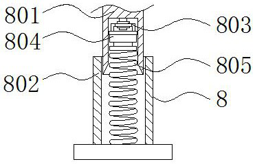
The invention relates to a boring machine with an anti-passivation structure for machining. The boring machine comprises an equipment shell and a fine machining mechanism, a first multi-section hydraulic cylinder and a belt conveyor are sequentially arranged on the lower wall of the interior of the equipment shell from the middle to the front side and the rear side, a supporting plate is connected to the upper end of the belt conveyor, and a groove plate is placed at the upper end of the supporting plate; and a connecting shaft and a clamping and feeding mechanism are sequentially arranged on the upper wall of the interior of the equipment shell from the middle to the left side and the right side, a pressing and fixing mechanism is arranged at the lower end of the connecting shaft, and a first motor is installed on one side of the connecting shaft. The boring machine has the beneficial effects that a third motor drives a screw rod to rotate to discharge metal chips generated during grooving of a rough cutter, and the situation that a large number of metal chips are accumulated at the rough cutter to affect machining of a groove plate at the rough cutter, meanwhile, the cutting resistance of the groove plate at the rough cutter can be increased, the rough cutter is prone to passivation, and the service life of the rough cutter is shortened is prevented.

Description

technical field [0001] The invention relates to the technical field of mechanical processing, in particular to a boring machine with an anti-passivation structure for mechanical processing. Background technique [0002] Slot plate is a kind of mechanical part commonly used in mechanical processing. During the processing of slot plate, a boring machine is needed to groove the surface of the metal plate, so boring machine is a kind of mechanical equipment commonly used in mechanical processing. [0003] Existing boring machines will produce a lot of metal shavings at the contact between the tool and the groove plate during the processing of the groove plate. These metal shavings accumulate at the tool and can interfere with the operation of the tool. At the same time, the tool is easy to process in the metal shavings for a long time There is a passivation problem. Contents of the invention [0004] The purpose of the present invention is to provide a boring machine with an ...

Claims


Application Information

Patent Timeline
Patent Type & Authority Applications(China)
IPC IPC(8): B23B41/00B23Q3/08B23Q3/06B23Q11/00B23Q11/10
CPCB23B41/00B23Q3/088B23Q3/062B23Q3/067B23Q11/0042B23Q11/10B23B2220/12B23B2220/445
Inventor 李颖琼陈静黄小蕊
Owner 东莞市达盛机电设计有限公司
Learn More