A support device for textile machinery

A technology of supporting device and textile machinery, applied in the directions of mechanical cleaning, textile and papermaking, transportation and packaging, etc., can solve problems such as inconvenience of use, and achieve the effect of ease of use, avoidance of excessive cleaning, and uniform cleaning effect

Active Publication Date: 2021-12-17
南通科健纺织有限公司
View PDF5 Cites 0 Cited by
  • Summary
  • Abstract
  • Description
  • Claims
  • Application Information

AI Technical Summary

Problems solved by technology

[0005] The purpose of the present invention is to solve the problem that most traditional rolling devices are inconvenient to use, and to provide a support device for textile machinery that is more convenient to use

Method used


Image

  • A support device for textile machinery
  • A support device for textile machinery
  • A support device for textile machinery

Examples


Embodiment 1

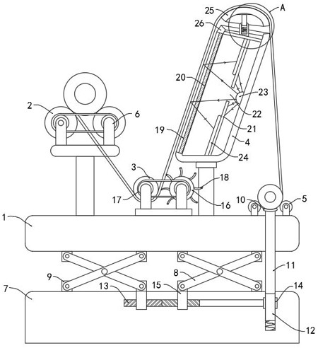
[0029] Such as Figure 1-2 As shown, a supporting device for a textile machine includes a horizontally arranged console 1, on which two driving rollers 2 arranged side by side, a steering roller 3, a light box 4 and two The accommodating roller 5 that is arranged side by side, above is prior art, does not repeat too much here.

[0030] The ends of the driving roller 2, the diverting roller 3 and the containing roller 5 are all rotatably connected with a strut 6, and the lower end of the strut 6 at the end of each driving roller 2 is jointly fixedly connected with a horizontally arranged bearing plate, and the bearing plate passes through its lower end vertically. The vertically arranged struts are fixedly connected to the console 1, and the other ends of the struts 6 at the ends of the steering roller 3 and the storage roller 5 are all fixedly connected to the console 1;

[0031] A support mechanism is provided below the console 1 to support the entire console, including a su...

Embodiment 2

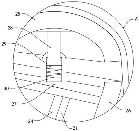
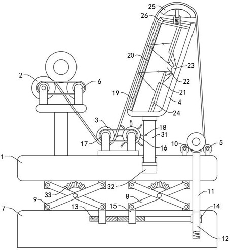
[0042] Such as image 3 As shown, the difference from Embodiment 1 is that the lower end of the light box 4 is connected with a connecting rod 31 extending into the operating table 1, and the operating table 1 is provided with a stabilizing groove 32 that is sealingly and slidingly connected with the connecting rod 31. An elastic bellows 33 is arranged between the two rotating plates 8 , and the two ends of the elastic bellows 33 are respectively fixedly connected to the upper side walls of the two rotating plates 8 , and the elastic bellows 33 communicates with the stabilizing groove 32 through a conduit.

[0043] When in use, the initial height of the light box 4 is relatively low, which can make it easier for the staff to wind the cloth through the upper end of the light box 4 to the turning roller 3. When the console 1 rises, the gas in the elastic bellows 33 will Squeezed into the stable groove 32, further pushing the light box 4 to move upwards, the cloth can be graduall...


PUM


Abstract

The invention belongs to the field of textile machinery, and in particular relates to a supporting device for textile machinery, which includes a horizontally arranged operating table, on which two drive rollers arranged side by side, a steering roller, and a The light box and two holding rollers arranged side by side, the ends of the driving roller, the steering roller and the holding roller are all rotatably connected with a strut, and the lower ends of the struts at the end of each driving roller are jointly fixedly connected with a horizontal setting The bearing plate is fixedly connected to the operating platform through the vertically arranged support rod at the lower end of the bearing plate, and the other ends of the supporting rods at the ends of the steering roller and the containing roller are fixedly connected to the operating platform. In the present invention, when the shell cover in the adjustment mechanism is moved upwards to make the cloth tense, the air pressure in the stabilizing tank will play a certain buffering effect, which can prevent the cloth from being too tight and cause the cloth to be seriously deformed and cannot be recovered. While cleaning, the original quality of the fabric is effectively protected.

Description

technical field [0001] The invention belongs to the field of textile machinery, in particular to a supporting device for textile machinery. Background technique [0002] In the production and processing of textiles, it is often necessary to use various processing machines, including sizing machines, looms and mercerizing machines. The last step after processing the cloth is to roll the cloth. The fabric is unloaded from the drum. [0003] The height of most traditional rolling equipment is fixed. However, during the rolling process, the staff often needs to perform winding and straightening operations on the console. After the coiling is completed, it is necessary to clean the surface of the console with a broom. Different jobs have different requirements for the height of the operating table. The broom is more convenient for cleaning the lower height of the table. The fixed height of the operating table is not convenient for cleaning tools such as brooms, and the cloth gen...

Claims


Application Information

Patent Timeline
Patent Type & Authority Patents(China)
IPC IPC(8): D06G1/00B65H20/02B65H23/038B65H18/20
CPCD06G1/00B65H20/02B65H23/038B65H18/20B65H2701/174
Inventor 王磊
Owner 南通科健纺织有限公司
Why Eureka
Try Eureka