Pressurizing and speeding-up loop and pressurizing and speeding-up method for hydraulic stand column

A hydraulic column and circuit technology, applied in the field of hydraulic system, can solve the problems affecting the total rack shifting time, restricting the initial support pressure and high pressure, and achieve the effects of low cost, increasing column lifting speed and shortening boosting time.

Pending Publication Date: 2021-11-19
TAIYUAN UNIVERSITY OF SCIENCE AND TECHNOLOGY +1
View PDF0 Cites 1 Cited by
  • Summary
  • Abstract
  • Description
  • Claims
  • Application Information

AI Technical Summary

Problems solved by technology

With the development of hydraulic supports with large mining heights, the demand for the initial support force of the rodless chamber of the hydraulic column continues to increase. Since the working pressure of the unloading valve of the general emulsion pump station is about 31.5MPa, the initial support pressure is lower than the actual working pressure. The working pressure of the liquid pump station restricts the increase of the initial support pressure; secondly, when the vertical column is lowered by the large mining height hydraulic support, the rod chamber of the column has the characteristics of small flow rate and high pressure. At present, the working pressure of the emulsion pump station is 31.5MPa , while restricting the development of the rapid descent of the hydraulic support
In the third aspect, during the moving process of the hydraulic support, after the stages of lowering, pushing, pulling, raising the column and boosting the pressure, due to the elastic deformation of the long liquid supply hose, the time in the boosting stage is longer, which will directly affect the total moving frame. time

Method used


Image

  • Pressurizing and speeding-up loop and pressurizing and speeding-up method for hydraulic stand column

Examples


Embodiment Construction

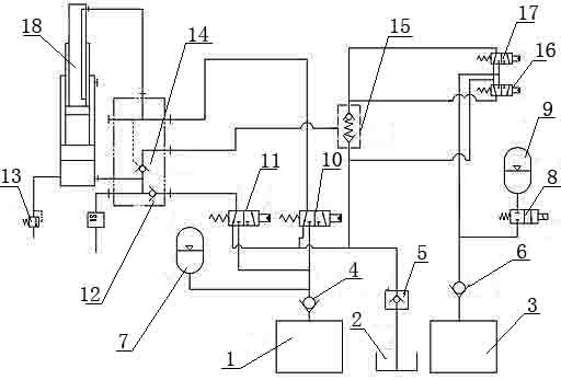
[0024] Attached below figure 1 The present invention is described in further detail with embodiment 1:

[0025] Such as figure 1 As shown, a hydraulic column pressurization speed-up circuit is connected with the hydraulic column 18, including 1 booster pump station, 2 oil tanks, 3 high-pressure pump stations, 4 first one-way valves, 5 liquid return circuit breaker valves, 6 second Check valve, 7 first accumulator, 8 electromagnetic reversing valve, 9 second accumulator, 10 first electro-hydraulic reversing valve, 11 second electro-hydraulic reversing valve, 12 third one-way valve, 13 Safety valve, 14 hydraulic control check valve, 15 bypass valve, 16 third electro-hydraulic directional valve, 17 fourth electro-hydraulic directional valve;

[0026] The rodless cavity of the hydraulic column 18 is connected with the liquid inlet of the safety valve 13 and the liquid outlet of the hydraulic control check valve 14 and the third check valve 12, and the liquid inlet of the hydraul...


PUM


Abstract

The invention provides a pressurizing and speeding-up loop for a hydraulic stand column, which is connected with the hydraulic stand column. A rodless cavity of the hydraulic stand column is connected with a hydraulic control one-way valve and a third one-way valve, the hydraulic control one-way valve is connected with a bypass valve, one end of the bypass valve is connected with an oil tank, the other end of the bypass valve is connected with a high-pressure pump station through a third electro-hydraulic reversing valve and a fourth electro-hydraulic reversing valve, and a second energy accumulator is arranged on a connecting line; the third one-way valve is connected with a second electro-hydraulic reversing valve, one end of the second electro-hydraulic reversing valve is connected with the oil tank, the other end of the second electro-hydraulic reversing valve is connected with a booster pump station, and a first energy accumulator is arranged on a connecting line connecting the second electro-hydraulic reversing valve and the booster pump station; and a rod cavity of the hydraulic stand column is connected with the hydraulic control one-way valve and a first electro-hydraulic reversing valve, one end of the first electro-hydraulic reversing valve is connected with the oil tank, and the other end of the first electro-hydraulic reversing valve is connected with the booster pump station. The initial supporting force of the hydraulic stand column can be effectively improved, the descending speed of the hydraulic stand column can be accelerated, the time of a pressure rising stage can be shortened, meanwhile, the pressurizing and speeding-up loop for the hydraulic stand column is used for column lifting of a hydraulic support, so that energy is recycled, and energy is saved.

Description

technical field [0001] The invention belongs to the technical field of hydraulic systems, and in particular relates to a pressurization speed-up circuit and a pressurization speed-up method of a hydraulic column. Background technique [0002] Underground coal mining in fully mechanized mining faces requires hydraulic supports as safety support equipment, and the support force of hydraulic supports to the coal roof is very important for operation safety. With the development of hydraulic supports with large mining heights, the demand for the initial support force of the rodless chamber of the hydraulic column continues to increase. Since the working pressure of the unloading valve of the general emulsion pump station is about 31.5MPa, the initial support pressure is lower than the actual working pressure. The working pressure of the liquid pump station restricts the increase of the initial support pressure; secondly, when the vertical column is lowered by the large mining hei...

Claims


Application Information

Patent Timeline
Patent Type & Authority Applications(China)
IPC IPC(8): F15B21/08F15B1/033F15B11/042F15B11/044F15B11/08F15B13/04E21D15/44E21D15/50
CPCF15B21/087F15B1/033F15B1/024F15B11/0426F15B11/044F15B11/08F15B13/0401E21D15/44E21D15/50
Inventor 李坤李永堂梁涛王永辉仉志强刘志奇王鲁军
Owner TAIYUAN UNIVERSITY OF SCIENCE AND TECHNOLOGY
Why Eureka
Try Eureka