
Phase laser distance measuring device and method for coarse and fine measuring tape difference frequency modulation and demodulation

A technology of phase laser distance measurement and ruler measurement, which is applied in measuring devices, electromagnetic wave re-radiation, radio wave measurement systems, etc. It can solve the problems of difficult to further improve the measurement range, difficult phase extraction, and decreased interference signal-to-noise ratio

Pending Publication Date: 2021-11-19
HARBIN INST OF TECH
View PDF5 Cites 0 Cited by
  • Summary
  • Abstract
  • Description
  • Claims
  • Application Information

AI Technical Summary

Problems solved by technology

However, due to the difference in the optical path of the measurement light and the reference light, when the optical path difference is greater than the coherence length, the interference signal-to-noise ratio decreases and it is difficult to perform phase extraction
Therefore, this method is limited by the coherence length. While ensuring high-precision measurement, its measurement range is limited to several kilometers and it is difficult to further improve it.

Method used


Image

  • Phase laser distance measuring device and method for coarse and fine measuring tape difference frequency modulation and demodulation
  • Phase laser distance measuring device and method for coarse and fine measuring tape difference frequency modulation and demodulation
  • Phase laser distance measuring device and method for coarse and fine measuring tape difference frequency modulation and demodulation

Examples


specific Embodiment 1

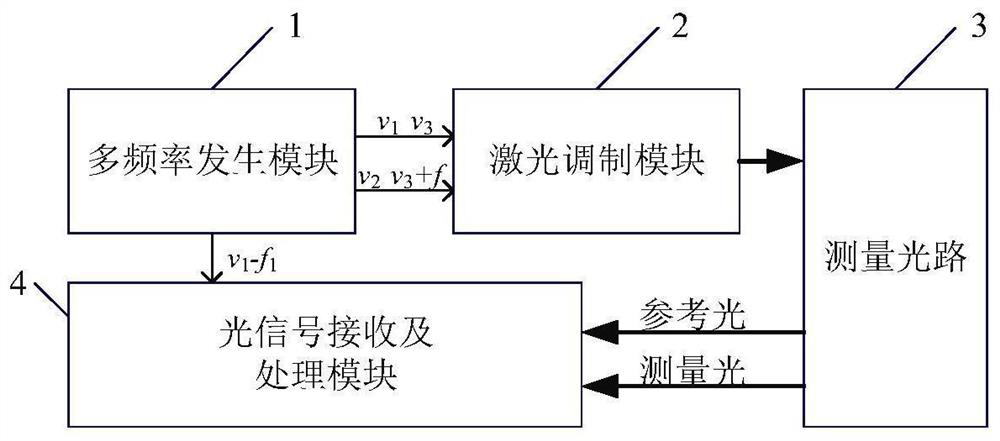
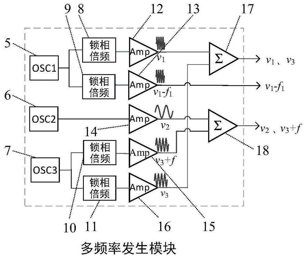
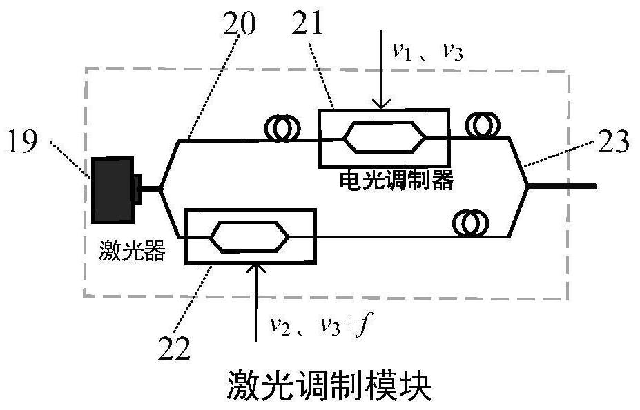
[0053] according to Figure 1 to Figure 5 shown, refer to Figure 1 to Figure 5As shown, the phase laser distance measuring device for the difference frequency modulation and demodulation of the coarse and fine scales includes a multi-frequency generation module 1, a laser modulation module 2, a measurement optical path 3 and an optical signal receiving and processing module 4. The multi-frequency generation module 1 generates three Two outputs, two of which are input to the laser modulation module 2 to modulate the laser, and the other input to the optical signal processing and receiving module 4, the output light of the laser modulation module is input to the measurement optical path 3, and the two output lights of the measurement optical path 3 are respectively Inputting the measuring light and the reference light to the optical signal receiving and processing module 4 for phase measurement;

[0054] The multi-frequency generation module 1 includes No. 1 crystal oscillator...


PUM


Abstract

The invention relates to a phase laser distance measuring device and a phase laser distance measuring method for coarse and fine measuring tape difference frequency modulation and demodulation. The distance measuring device comprises a multi-frequency generation module, a laser modulation module, a measuring light path and a light signal receiving and processing module. The distance measuring method comprises the following steps that a laser and a multi-frequency generation module are turned on; the laser is modulated to generate an accurate measurement ruler c / v1, a secondary rough measurement ruler c / v2 and a rough measurement ruler c / f, wherein the rough measurement ruler c / f is generated by performing difference frequency modulation through signals with the frequencies of v3 and v3+f; the laser is divided into reference light and measuring light and the distance is measured; and difference frequency demodulation with the frequency of v1-f1 is conducted on the fine measurement ruler, a difference frequency signal f1 is detected to obtain a fine measurement result, the secondary coarse measurement ruler c / v2 and the coarse measurement ruler c / f are detected to obtain a phase, and phase difference data is synthesized to obtain a measured distance. According to the invention, limitations of laser interference coherence length, detection device bandwidth and modulation bandwidth are broken through, and submillimeter and even micron-level accurate measurement can be realized in the measurement range requirement of hundreds of thousands of kilometers in the future.

Description

technical field [0001] The invention relates to the technical field of absolute distance laser measurement, and relates to a phase laser distance measuring device and a distance measuring method for coarse and fine ruler difference frequency modulation and demodulation. Background technique [0002] Laser ranging technology is widely used in the fields of large-scale equipment manufacturing, spacecraft deep space navigation, rendezvous and docking, and distributed formation satellites due to its advantages of high measurement accuracy, strong anti-interference ability, high spatial-temporal and vertical resolution, etc. It is an indispensable key technology in the research of aerospace, major scientific installations and national economic development. With the development of science and technology, especially the rapid development of aerospace technology, higher performance requirements are put forward for the measurement range, measurement accuracy and stability of measurem...

Claims


Application Information

Patent Timeline
IPC IPC(8): G01S17/36
CPCG01S17/36
Inventor 杨宏兴李婧胡鹏程邢旭谭久彬
Owner HARBIN INST OF TECH
Learn More