
Fuel cell air system decoupling control method, device and storage medium

A fuel cell and air system technology, applied in fuel cells, electrical components, circuits, etc., can solve the problems of slow response speed of air flow and air pressure, complicated process of solving coefficients, and poor practicability, so as to achieve easy production and acquisition and quick response time, high accuracy

Active Publication Date: 2022-07-26
WUXI WEIFU HIGH TECH CO LTD
View PDF9 Cites 0 Cited by
  • Summary
  • Abstract
  • Description
  • Claims
  • Application Information

AI Technical Summary

Problems solved by technology

The existing technology uses advanced control methods, such as transfer function decoupling, feedback linearization, active disturbance rejection control, etc., which can achieve the effect of decoupling control to a certain extent, but it is relatively complicated and less practical
Among them, the patent CN111293333A performs decoupling control by solving the correction coefficient, and the process of solving the coefficient is relatively complicated; the patent CN110970642A uses the flow difference as the PID correction of the throttle valve opening and the pressure difference as the PID correction of the air compressor speed. The modified PID decoupling method has a slightly slower response speed to air flow and air pressure; the patent CN111403783A uses self-interference control to achieve decoupling, which is more theoretical but less practical

Method used


Image

  • Fuel cell air system decoupling control method, device and storage medium
  • Fuel cell air system decoupling control method, device and storage medium
  • Fuel cell air system decoupling control method, device and storage medium

Examples


Embodiment Construction

[0041] In order to make the objectives, technical solutions and advantages of the present invention clearer, the present invention will be further described in detail below with reference to the accompanying drawings and embodiments. It should be understood that the specific embodiments described herein are only used to explain the present invention, but not to limit the present invention.

[0042] A schematic diagram of the fuel cell air system is shown in figure 1 , including air filter, air compressor, intercooler, humidifier, protection valve, pressure sensor and flowmeter measurement ( figure 1 (not shown in the figure), throttle valve and ECU controller, etc.; for the actual stack, the air needs to go through a series of processes of filtration, pressurization, cooling, and humidification to ensure the high-efficiency chemical reaction of the stack;

[0043] The air filter is installed at the front end, and its function is to filter impurities and harmful gases in the a...


PUM


Abstract

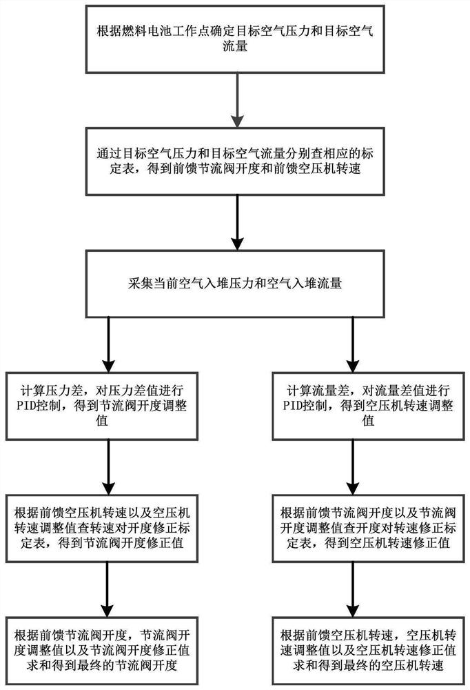
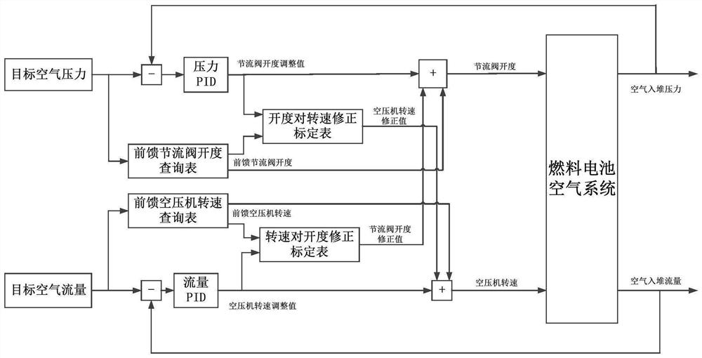
The present invention provides a method for decoupling an air system of a fuel cell, comprising: determining a corresponding target air pressure and a target air flow according to a fuel cell operating point; checking the corresponding calibration tables through the target air pressure and the target air flow, respectively, to obtain a feedforward Throttle valve opening and feedforward air compressor speed; real-time air inlet pressure and air inlet flow rate are obtained through acquisition; the difference between target air pressure and air inlet pressure is calculated, and PID control is performed on the pressure difference. Obtain the throttle valve opening adjustment value; check the corresponding opening to speed correction calibration table through the feedforward throttle valve opening and throttle valve opening adjustment value to obtain the air compressor speed correction value; calculate the target air flow and The difference value of the air flow into the stack, and PID control is performed on the flow difference to obtain the air compressor speed adjustment value; through the feedforward air compressor speed and air compressor speed adjustment value, check the corresponding speed to the opening correction calibration table , get the throttle valve opening correction value; sum to get the final throttle valve opening; sum to get the final air compressor speed. The invention is simple and easy to implement, has strong practicability and high accuracy.

Description

technical field [0001] The invention relates to the field of fuel cell air system control, in particular to a fuel cell air system decoupling control method. Background technique [0002] Facing the severe requirements of environmental pollution, the automotive market is transforming from traditional chemical energy to new energy. Among them, the hydrogen fuel cell system has been developed by major automakers all over the world due to its advantages of zero emission, high efficiency and wide range of sources. The air supply system involved is a unit that consumes a large amount of power as a system accessory. The control and optimization of its own system is of great significance to the stable operation and output efficiency of the entire fuel cell system. [0003] Air system control involves the control of two important parameters: air pressure and air flow. The two parameters of air pressure and air flow are highly coupled in the actual control process, and it is diffic...

Claims


Application Information

Patent Timeline
Patent Type & Authority Patents(China)
IPC IPC(8): H01M8/0438H01M8/04746H01M8/04992
CPCH01M8/04388H01M8/04992H01M8/04753H01M8/04432Y02E60/50
Inventor 单亚飞邵力成毛强陈杰李刚
Owner WUXI WEIFU HIGH TECH CO LTD
Learn More