
Aluminum alloy cutting equipment for door and window production

A cutting equipment, aluminum alloy technology, applied in metal processing equipment, shearing equipment, shearing devices and other directions, can solve the problems affecting cutting accuracy, delay efficiency, troublesome operation, etc., to reduce labor intensity, ensure accuracy, guarantee The effect of accuracy

Inactive Publication Date: 2021-11-23
徐州市固塑建筑材料有限公司
View PDF0 Cites 0 Cited by
  • Summary
  • Abstract
  • Description
  • Claims
  • Application Information

AI Technical Summary

Problems solved by technology

[0003] There are many types of existing doors and windows, including aluminum alloy doors and windows. During the production and processing of existing aluminum alloy doors and windows, it is often necessary to cut aluminum alloy profiles, which requires the use of cutting equipment. In the process of cutting alloy profiles, the cut aluminum alloy profiles often need to be manually transferred, and placed in the transfer frame for orderly placement. After a certain amount is stored in the transfer frame, the transfer is carried out. The process of storing in the transfer box is done manually, which is cumbersome to operate, resulting in high fatigue strength and delaying efficiency, and there are debris in the cutting process. The debris is easy to cause irregular arrangement of the profiles, thus affecting the cutting accuracy

Method used


Image

  • Aluminum alloy cutting equipment for door and window production
  • Aluminum alloy cutting equipment for door and window production
  • Aluminum alloy cutting equipment for door and window production

Examples


Embodiment Construction

[0025] The following will clearly and completely describe the technical solutions in the embodiments of the present invention with reference to the accompanying drawings in the embodiments of the present invention. Obviously, the described embodiments are only some, not all, embodiments of the present invention.

[0026] In describing the present invention, it should be understood that the terms "upper", "lower", "front", "rear", "left", "right", "top", "bottom", "inner", " The orientation or positional relationship indicated by "outside", etc. is based on the orientation or positional relationship shown in the drawings, and is only for the convenience of describing the present invention and simplifying the description, rather than indicating or implying that the referred device or element must have a specific orientation, so as to Specific orientation configurations and operations, therefore, are not to be construed as limitations on the invention.

[0027] In the description...


PUM


Abstract

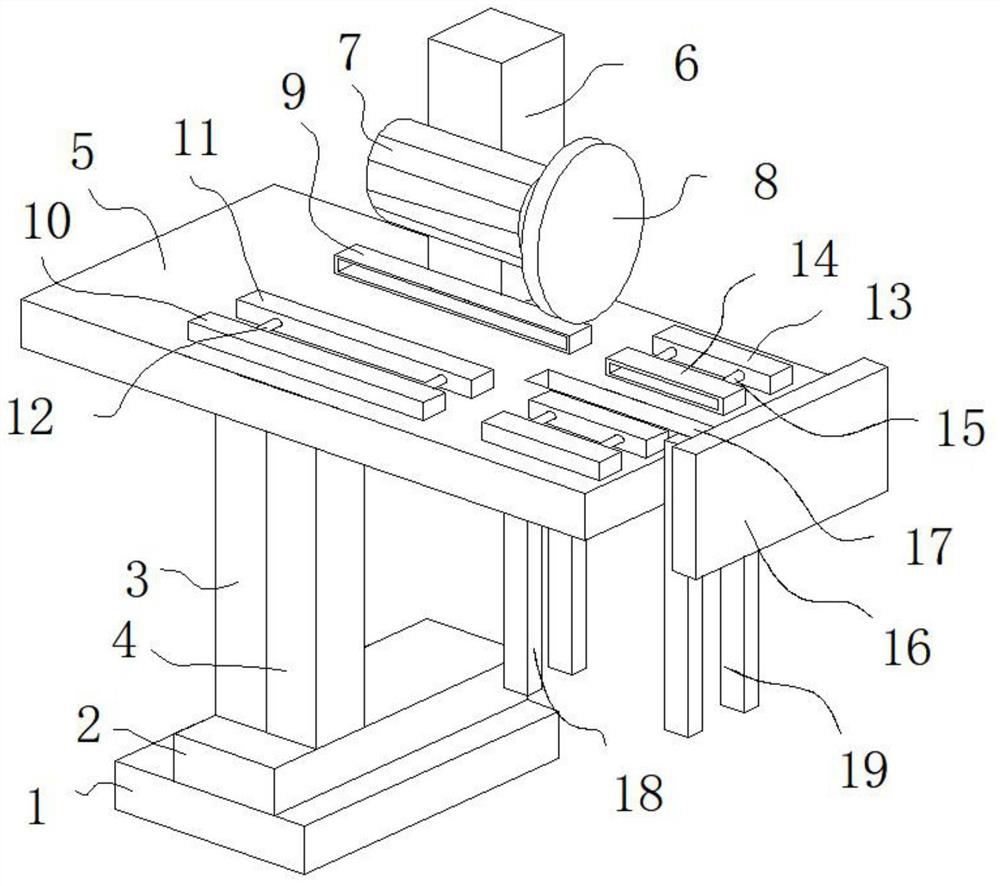
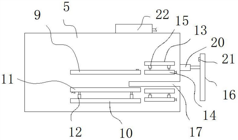
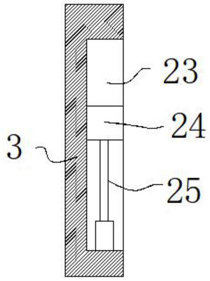
The invention belongs to the field of door and window production, and particularly relates to aluminum alloy cutting equipment for door and window production. The aluminum alloy cutting equipment comprises a base, a fixing plate is fixedly mounted at the top of the base, a supporting column is connected to the top of the fixing plate, a lifting column is connected to the outer wall of the supporting column, and a top plate is fixedly connected to the top of the lifting column. According to the aluminum alloy cutting equipment, after cutting is completed, cut aluminum alloy profiles can be guided into a notch in a pushing mode, then aluminum alloy profile grooves can be guided into a storage frame under the guiding effect of a first limiting rod and a second limiting rod, manual operation is not needed, under effective limiting, the aluminum alloy profiles can be stacked in order, and meanwhile, along with the cutting adjustment of different lengths, a second limiting rod can also be adjusted along with the cutting adjustment of different lengths, so that the limiting accuracy of the cut profile is effectively guaranteed, the labor intensity of workers can be greatly reduced, integrated operation is achieved, and the cutting efficiency is effectively improved.

Description

technical field [0001] The invention relates to the field of door and window production, in particular to an aluminum alloy cutting device for door and window production. Background technique [0002] Doors and windows are divided into enclosure components or partition components according to their positions, and have different design requirements to have functions such as heat preservation, heat insulation, sound insulation, waterproof, and fire prevention. The new requirement is energy saving. The lost heat accounts for about 25% of the total heating heat consumption. The airtight requirements of doors and windows is an important content in energy-saving design. Doors and windows are an important part of the building envelope system. The second function: doors and windows are an important part of architectural modeling (virtual-real contrast, rhythmic artistic effect, play an important role) so their shape, size, proportion, arrangement, color, shape, etc. have a great i...

Claims


Application Information

Patent Timeline
IPC IPC(8): B23D19/00B23D33/02B23Q11/08B23Q11/00
CPCB23D19/00B23D33/02B23Q11/08B23Q11/0046
Inventor 刘东
Owner 徐州市固塑建筑材料有限公司
Learn More