Unlock instant, AI-driven research and patent intelligence for your innovation.

Rear-mounted AEBS system

A technology of sensing layer and decision-making layer, which is applied in the field of post-installation AEBS system, can solve problems such as inapplicability, and achieve the effect of high independence and wide application

Inactive Publication Date: 2021-11-23
SHENZHEN BOYONG TECH
View PDF6 Cites 0 Cited by
  • Summary
  • Abstract
  • Description
  • Claims
  • Application Information

AI Technical Summary

Problems solved by technology

[0003] At present, most of the models equipped with AEBS have been equipped by the main engine factory before leaving the factory, that is, the configuration of this function has been considered in the design stage. This kind of AEBS technical solution controls the controller through radar and camera, so as to execute ESC or electro-hydraulic system. The actuator of this type of technical solution is the ESC or electro-hydraulic brake system in the brake system. These two types of actuators are the key parts of the brake system. They need a lot of actual vehicle matching work before they can be finalized. Then For a large number of old models without AEBS function on the market, this solution is not applicable. Therefore, we propose a rear-mounted AEBS system

Method used


Image

  • Rear-mounted AEBS system
  • Rear-mounted AEBS system
  • Rear-mounted AEBS system

Examples


Embodiment 1

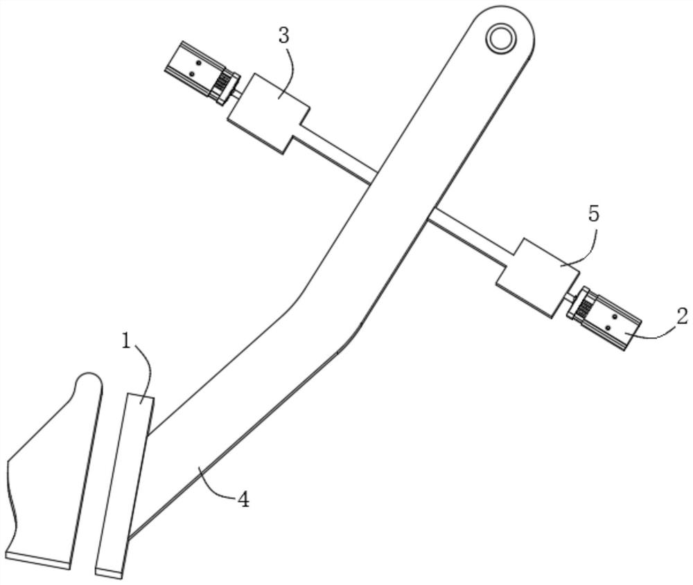
[0020] see Figure 1-2 , an after-installed AEBS system in the figure, including the induction layer, the signal of the induction layer is connected to the decision-making layer; it also includes the brake pedal 1 and the motor 2 controlled by the decision-making layer; the motion component 3; the motion component 3 is used to cooperate with the motor 2Actuate the brake pedal 1.

[0021] see figure 2 , the moving assembly 3 in the figure includes a brake pedal arm 4 that is rotatably connected to the vehicle body, the end of the brake pedal arm 4 is connected and fixed to the brake pedal 1, and the output shaft of the motor 2 is connected to a connecting mechanism 5, which is connected to the The brake pedal arm 4 is connected.

[0022] see figure 2 , the motor 2 in the illustration provides power support through the car body system, and at the same time, the sensing layer includes radar and camera, and at the same time, the decision-making layer includes a controller wit...

Embodiment 2

[0026] see figure 1 with image 3 , an after-installed AEBS system in the figure, including the induction layer, the signal of the induction layer is connected to the decision-making layer; it also includes the brake pedal 1 and the motor 2 controlled by the decision-making layer; the motion component 3; the motion component 3 is used to cooperate with the motor 2Actuate the brake pedal 1.

[0027] see image 3 , the moving assembly 3 in the figure includes a brake pedal arm 4 that is rotatably connected to the vehicle body, the end of the brake pedal arm 4 is connected and fixed to the brake pedal 1, and the output shaft of the motor 2 is connected to a connecting mechanism 5, which is connected to the The brake pedal arm 4 is connected.

[0028] see image 3 , the brake pedal arm 4 in the illustration is provided with a through hole.

[0029] In this embodiment, the specific connection manner between the connecting mechanism 5 and the brake pedal 1 may be a fixed rigid ...


PUM


Abstract

The invention discloses a rear-mounted AEBS system comprising an induction layer which is in signal connection with a decision-making layer; The system further comprises a brake pedal, a motor controlled by the decision-making layer, and a motion assembly; the motion assembly is used for being matched with the motor to drive the brake pedal, road information is picked up through the induction layer, fed back to the decision-making layer for analysis and judgment, the motor is driven to drive the motion mechanism to drive the brake pedal, and the active braking function is achieved. The system directly acts on the brake pedal or a rotating shaft, does not intervene in an original brake system, and is independently mounted; functions of the braking system of the original vehicle are not affected; the application range is wide; the system is capable of being used for rear installation of all vehicles with brake pedals in the market, high in independence and free of influence on the original vehicle brake system.

Description

technical field [0001] The invention relates to the technical field of AEBS systems, in particular to an aftermarket AEBS system. Background technique [0002] AEBS (Autonomous Emergency Braking System) is a supporting system in the field of autonomous driving. The AEBS system uses radar or camera to measure the distance to the vehicle in front or obstacles, and then uses the data analysis module to compare the measured distance with the warning distance and safety distance. Even if the driver does not have time to step on the brake pedal, the AEB system will drive the actuator to automatically brake the car, thus ensuring safe travel. [0003] At present, most of the models equipped with AEBS have been equipped by the main engine factory before leaving the factory, that is, the configuration of this function has been considered in the design stage. This kind of AEBS technical solution controls the controller through radar and camera, so as to execute ESC or electro-hydraul...

Claims


Application Information

Patent Timeline
IPC IPC(8): B60T7/22B60T13/74
CPCB60T7/22B60T13/74
Inventor 马光项春亮黄耿青王冬亮
Owner SHENZHEN BOYONG TECH
Features
  • R&D
  • Intellectual Property
  • Life Sciences
  • Materials
  • Tech Scout
  • Unparalleled Data Quality
  • Higher Quality Content
  • 60% Fewer Hallucinations
Learn More