
Lever principle water diversion conversion gravitational potential energy power generation device e

A power generation device, gravitational potential energy technology, applied in electromechanical devices, valve devices, valve operation/release devices, etc., can solve the problems of large resistance, low water flow energy, and high cost of production, and achieve high reuse rate and debugging. Convenience and simplicity, low maintenance cost

Inactive Publication Date: 2021-11-23
杨添乐
View PDF4 Cites 0 Cited by
  • Summary
  • Abstract
  • Description
  • Claims
  • Application Information

AI Technical Summary

Problems solved by technology

[0004] However, there are still some disadvantages in the existing power generation device. The traditional traditional water wheel has large wheels, the main purpose is to lift water, and the speed is slow. , the power generation potential is limited. Even if the existing water turbine drives the generator to generate electricity, it is driven by strong water pressure. The cost is high, and the power generation efficiency of the water wheel is low. For this reason, we propose a kind of lever principle water diversion conversion gravitational potential energy power generation device

Method used


Image

  • Lever principle water diversion conversion gravitational potential energy power generation device e
  • Lever principle water diversion conversion gravitational potential energy power generation device e
  • Lever principle water diversion conversion gravitational potential energy power generation device e

Examples


Embodiment Construction

[0030] In order to make the technical means, creative features, goals and effects achieved by the present invention easy to understand, the present invention will be further elaborated below in conjunction with specific embodiments, but the following embodiments are only preferred embodiments of the present invention, not all. Based on the examples in the implementation manners, other examples obtained by those skilled in the art without making creative efforts all belong to the protection scope of the present invention. The experimental methods in the following examples, unless otherwise specified, are conventional methods, and the materials, reagents, etc. used in the following examples, unless otherwise specified, can be obtained from commercial sources.

[0031] Example:

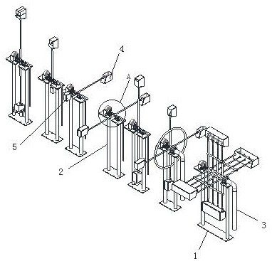
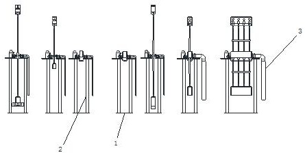
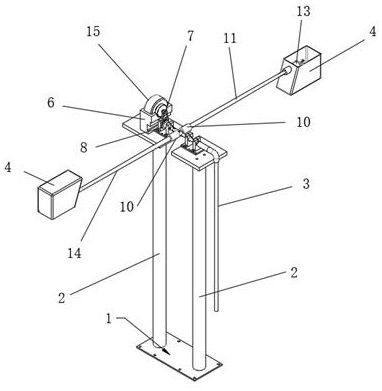
[0032] Such as figure 1 - Image 6 As shown, it is a kind of leverage principle water diversion conversion gravity potential energy power generation device realized by the present invention. A leverage p...


PUM


Abstract

The invention discloses a lever principle water diversion conversion gravitational potential energy power generation device. The lever principle water diversion conversion gravitational potential energy power generation device comprises a power generation device body, a fixing frame is arranged on the power generation device body, a supporting plate is arranged on the fixing frame, a bearing fixing seat is arranged on the supporting plate, and a bearing is arranged on the bearing fixing seat in a supporting mode. The power generation device body is connected with a hollow pipe connected with a high-level water source, a rotating joint is fixedly connected with the other end of the hollow pipe, a third hollow pipe is connected with other end of the rotating joint, a four-way pipeline is connected with the other end of the third hollow pipe through a bearing, the center end of the four-way pipeline is connected with a power generation device, the front end and the rear end of the four-way pipeline are connected with one-way check valves, and the other ends of the one-way check valves are connected with a first hollow pipe and a second hollow pipe. The end parts of the first hollow pipe and the second hollow pipe are connected with a gravity ball valve and a water storage tank. By means of the design, water is led to the highest point of the end of the second hollow pipe, conversion from gravitational potential energy to mechanical energy is maximized, efficiency is improved, installation is easy, and the problems that a whole waterwheel is complex in manufacturing and low in efficiency are solved.

Description

technical field [0001] The invention relates to the technical field of power generation, in particular to a leverage principle water diversion conversion gravity potential energy power generation device. Background technique [0002] Generators use power generation power devices to convert water energy, thermal energy of fossil fuels (coal, oil, natural gas, etc.), nuclear energy, solar energy, wind energy, geothermal energy, ocean energy, etc. There are not many resources and they are becoming increasingly depleted. Human beings have gradually used more renewable energy (water energy, solar energy, wind energy, geothermal energy, ocean energy, etc.) to generate electricity. [0003] For example, patent application 202011247220.6 discloses a small-sized impeller power generation device, which includes a device body. The device body includes a first pipe and a second pipe that communicates with the side wall of the first pipe and is arranged at a certain inclined angle. The i...

Claims


Application Information

Patent Timeline
IPC IPC(8): F03G3/00F16K1/14F16K31/44H02K7/18
CPCF03G3/00F16K1/14F16K31/44H02K7/1823
Inventor 杨添乐
Owner 杨添乐
Learn More