Sediment particle size monitoring device for river flow monitoring

Pending Publication Date: 2021-11-23
ZHENGZHOU XINGRUI WATER CONSERVANCY TECH
View PDF1 Cites 0 Cited by
  • Summary
  • Abstract
  • Description
  • Claims
  • Application Information

AI Technical Summary

Problems solved by technology

[0005] The object of the present invention is to provide a kind of sediment particle size monitoring device for river flow monitoring, aiming to solve the problem of river sediment in different regions in the prior art. When monitoring, it is often necessary to have different sizes of outer pipes to make the monitoring probe have a suitable area. This is very inconvenient for the regional monitoring management agency to reserve different types of outer pipes.

Method used


Image

  • Sediment particle size monitoring device for river flow monitoring
  • Sediment particle size monitoring device for river flow monitoring
  • Sediment particle size monitoring device for river flow monitoring

Examples


Embodiment 1

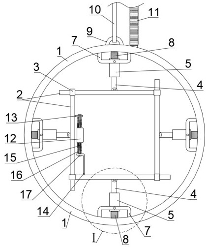
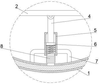
[0027] Such as Figure 1-3 As shown, a sediment particle size monitoring device for river flow monitoring includes a hollow ring 1 inside, and the inner wall of the ring 1 is uniformly fixedly connected with at least four mounting brackets along the circumferential direction. 7. Preferably, the mounting frame 7 is U-shaped, and a cylinder 5 is hinged on the mounting frame 7. One end of the cylinder 5 facing the mounting frame 7 is connected to the inside of the ring 1 through the first hose 8. The cylinder The inner part of the body 5 is provided with a piston part 6, and the piston part 6 is fixedly connected with a movable rod 4. The movable rod 4 passes through the other end of the cylinder body 5 and is hinged at the end of the movable rod 4 outside the cylinder body 5. Straight plate 2, wherein one end of each straight plate 2 is fixedly connected with sleeve body 3, and the other end of each straight plate 2 passes through the sleeve body 3 on the adjacent straight plate...

Embodiment 2

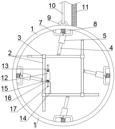
[0034] On the basis of Example 1, such as image 3 and 4 As shown, the present invention also includes a water-driven cleaning mechanism for cleaning the probe of the monitoring device body 12 through water driving. Specifically, the water-driven cleaning mechanism includes a connecting rod fixedly connected with the guide rod 15 18. A casing 19 is fixedly connected to the connecting rod 18, and a turbine assembly 20 is installed rotatably inside the casing 19. A water inlet 21 and a discharge port are opened on the casing 19, and the output end of the turbine assembly 20 is fixedly connected to There is a Y-shaped rod 22, and a steel wire rope 23 is fixedly connected to the Y-shaped rod 22. When the Y-shaped rod 22 follows the rotation of the turbine assembly 20, the steel wire rope 23 can be rotated along the surface of the probe of the monitoring device body 12.

[0035] When the water flows through the casing 19, the water flows into the casing 19 through the water inlet ...


PUM


Abstract

The invention provides a sediment particle size monitoring device for river flow monitoring, and relates to the technical field of sediment particle size monitoring. The sediment particle size monitoring device for river flow monitoring comprises an annular piece with a hollow interior; at least four mounting frames are uniformly and fixedly connected to the inner wall of the annular piece in the circumferential direction, cylinders are hinged to the mounting frames, the ends, facing the mounting frames, of the cylinders communicate with the interior of the annular part through first hoses, piston parts are movably arranged in the cylinders, and movable rods are fixedly connected to the piston parts; the movable rod penetrates through the other end of the barrel, and a straight plate is hinged to the end, located outside the barrel, of the movable rod; the regular polygon formed by all the straight plates can be proportionally reduced, so that silt at the cross sections of different areas can be conveniently monitored, the application range is wide, a monitoring management mechanism does not need to reserve monitoring devices of multiple models, the use is very flexible, and the use cost is further reduced.

Description

technical field [0001] The invention relates to the technical field of sediment particle size monitoring, in particular to a sediment particle size monitoring device for river flow monitoring. Background technique [0002] When monitoring the flow of a certain section of river, it is necessary not only to detect the flow velocity of the water, but also to monitor the condition of the section of the river through the particle size of the flowing sediment particles. Good monitoring of sediment needs to be placed in water. [0003] In the Chinese patent whose authorized announcement number is CN210982140U, a kind of sediment particle size monitoring device for river flow monitoring is disclosed, which includes an outer pipe and a plunger, and the transparent cover fixed above the inner part of the outer pipe is respectively equipped with The illuminating lamp and the monitoring probe, the inside of the tooth frame is meshed with the special-shaped gear fixed on the rotating sh...

Claims


Application Information

Patent Timeline
Patent Type & Authority Applications(China)
IPC IPC(8): G01N15/02G01F1/00G01F15/18B08B1/00
CPCG01N15/02G01F1/00G01F15/18B08B1/165
Inventor 王志勇郑凯陈卫芳孙建民雷成茂张曦明吴幸华张景
Owner ZHENGZHOU XINGRUI WATER CONSERVANCY TECH
Why Eureka
Try Eureka