
A method and system for denoising of magnetotelluric signals based on bi-lstm

A magnetotelluric and signal technology, applied in the field of magnetotelluric signal denoising based on Bi-LSTM, it can solve the problems of noise overprocessing, achieve high-precision noise prediction, improve computing efficiency, and optimize network parameters.

Active Publication Date: 2022-07-12
HUNAN NORMAL UNIVERSITY
View PDF6 Cites 0 Cited by
  • Summary
  • Abstract
  • Description
  • Claims
  • Application Information

AI Technical Summary

Problems solved by technology

Therefore, how to accurately predict the complex noise profile in the measured data, effectively complete the separation and removal of noise, and solve the problem of noise overprocessing in the prior art is an urgent need for consideration in the present invention.

Method used


Image

  • A method and system for denoising of magnetotelluric signals based on bi-lstm
  • A method and system for denoising of magnetotelluric signals based on bi-lstm
  • A method and system for denoising of magnetotelluric signals based on bi-lstm

Examples


Embodiment 1

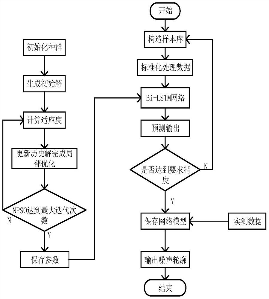
[0088] The Bi-LSTM-based magnetotelluric signal denoising method provided in this embodiment is essentially a NPSO-Bi-LSTM-based magnetotelluric signal denoising method. likefigure 1 As shown, the shown method includes the following steps:

[0089] Step 1: Take the amplitude of the time series of the magnetotelluric signal as the characteristic parameter, and construct a noise contour signal that contains a large amount of the weak signal and strong interference characteristics of the actual magnetotelluric signal, and add the two to obtain a noisy signal;

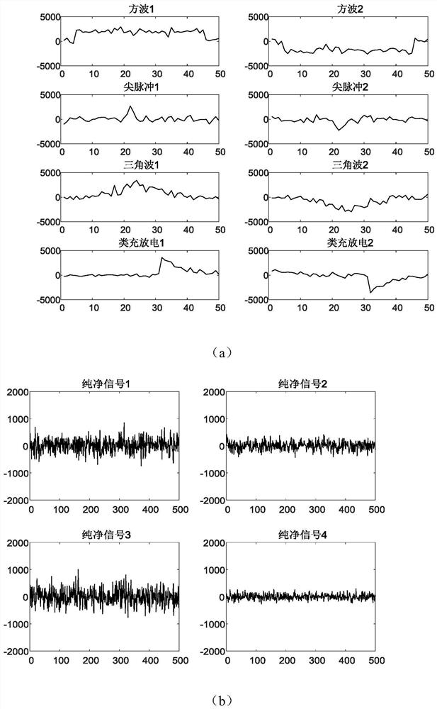
[0090] In order to better characterize the time-domain waveform characteristics of the measured magnetotelluric data, noise contour signals containing typical square waves, triangular waves and pulses were constructed respectively. -5 to 10 5 between;

[0091] Construct the pure interference signal as the pure signal. The length of the clean signal is 320000 and the amplitude is between -1000 and 1000; the sum of the no...

Embodiment 2

[0118] A magnetotelluric signal denoising system based on the NPSO-Bi-LSTM magnetotelluric signal denoising method provided in the above embodiment 1, including: a sample library building module, an NPSO parameter optimization module, a Bi-LSTM model building module, a prediction module modules, refactoring modules.

[0119] Among them, the sample library building module is used to construct the noise sample library and the pure signal sample library of the magnetotelluric signal.

[0120] NPSO parameter optimization module: used to find the optimal data segment division length and network parameters within a reasonable range, and select the optimal parameter combination to improve the prediction accuracy of the Bi-LSTM network.

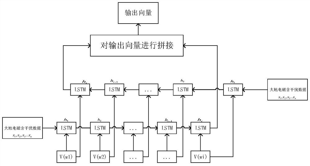
[0121] The Bi-LSTM model building block: used to define the input and output of the bidirectional long short-term memory neural network, and train the bidirectional long short-term memory neural network using the magnetotelluric noise signal and its ...


PUM


Abstract

The invention discloses a method and system for denoising a magnetotelluric signal based on Bi-LSTM. The invention constructs a large number of noise contours conforming to weak magnetotelluric signals and strong interference characteristics, and adds the two to obtain a noise-containing signal; The noisy signal is divided into the corresponding training set and test set according to the proportion, and the corresponding input and output of the network are defined. It is preferable to use NPSO to select the relevant parameters of the optimal bidirectional long short-term memory neural network, and then send the training set to the neural network. Perform training to obtain a prediction model; use the prediction model to predict the measured magnetotelluric data to obtain a noise profile; finally subtract the predicted noise profile from the measured magnetotelluric data to obtain a useful magnetotelluric signal. The present invention can effectively and accurately complete the prediction of the noise profile through the above method, thereby eliminating the noise in the noise-containing signal and retaining more useful magnetotelluric signals.

Description

technical field [0001] The invention belongs to the technical field of magnetotelluric signal processing, and in particular relates to a method and system for denoising of magnetotelluric signals based on Bi-LSTM. Background technique [0002] With the rapid development of social economy, my country's dependence on foreign energy and metal mineral resources has been increasing year by year. The shortage of mineral resources and the insufficient proved reserves of energy backup have become a major bottleneck restricting the development of the national economy. The magnetotelluric method (MT) is a geophysical exploration method proposed by the Soviet scholar Tikhon and the French scholar Cagiard in the early 1950s to study the electrical structure of the earth by using the natural alternating electromagnetic field. MT plays an important role in geophysical exploration due to its large exploration depth, low exploration cost, convenient construction, and mature data processing...

Claims


Application Information

Patent Timeline
Patent Type & Authority Patents(China)
IPC IPC(8): G01V3/38
CPCG01V3/38
Inventor 李晋汪嘉琳刘业成苏贵刘姗姗马翻红彭意群张贤
Owner HUNAN NORMAL UNIVERSITY
Learn More