A banknote turning channel structure

A channel structure and banknote technology, applied in the direction of processing coins or valuable banknotes, coin accepting devices, instruments, etc., can solve problems such as insufficient space and inability to place floating wheels, and achieve uniform power, cost realization, and guaranteed effectiveness. Effect

Active Publication Date: 2022-01-18
CASHWAY FINTECH CO LTD
View PDF9 Cites 0 Cited by
  • Summary
  • Abstract
  • Description
  • Claims
  • Application Information

AI Technical Summary

Problems solved by technology

[0004] However, the floating wheel has requirements for space. When turning the channel, there will often be insufficient space to place the floating wheel. How to design the channel in this case to ensure the efficient transmission of banknotes is a problem that those skilled in the art need to solve technical challenge

Method used


Image

  • A banknote turning channel structure
  • A banknote turning channel structure
  • A banknote turning channel structure

Examples


Embodiment Construction

[0033] The present invention will be described in further detail below in conjunction with the accompanying drawings and specific embodiments. It should be understood that the specific embodiments described here are only used to explain the present invention, not to limit the present invention.

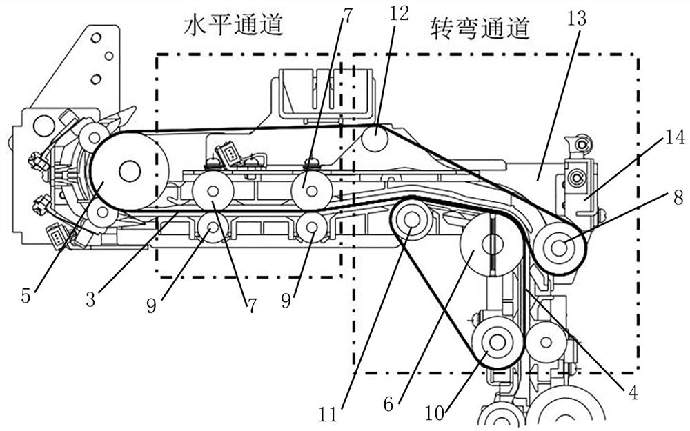
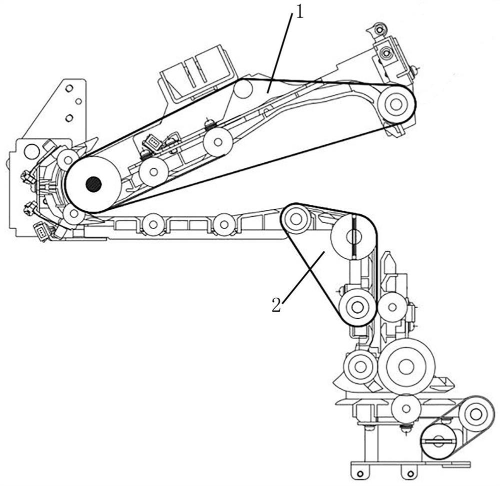
[0034] A banknote turning channel structure, including an upper channel assembly 1 located above and a lower channel assembly 2 located below, the upper channel assembly includes several upper transmission wheels and an upper belt 3, and the lower channel assembly includes several lower transmission wheels and a lower belt 4 , a transmission channel is formed between the upper belt and the lower belt, and the banknotes are transmitted between the upper belt and the lower belt; the use of the belt for transmission has changed the previous transmission method of using two transmission wheels up and down, reducing the risk of banknotes being jammed at the transmission wheel probability. ...


PUM


Abstract

The invention discloses a banknote turning channel structure, which comprises an upper channel assembly located above and a lower channel assembly located below, the upper channel assembly includes several upper transmission wheels and an upper belt, and the lower channel assembly includes several lower transmission wheels and a lower belt , a transmission channel is formed between the upper belt and the lower belt, and banknotes are transmitted between the upper belt and the lower belt; several upper driving wheels and several lower driving wheels are respectively provided with driving wheels, which are respectively upper driving wheels and lower driving wheels, and several The distribution of the lower driving wheels forms a triangular structure; several upper driving wheels also include the upper driving wheel and the steering wheel of the horizontal channel, and the upper belt realizes the connection of the steering wheel and the upper driving wheel. The configuration of double belts and double power makes the horizontal transmission and turning transmission power of banknotes more uniform. At the same time, it adopts the design of floating wheel structure and belt pressure structure, and uses belt pressure for grip transmission in places where there is insufficient space, ensuring the transmission of power. effectiveness.

Description

technical field [0001] The invention belongs to the field of financial self-service equipment, in particular to a banknote turning channel structure. Background technique [0002] The movement is the core module of the self-service teller machine, which undertakes the whole process of banknote circulation in the self-service teller machine. In view of actual needs, the movement also undertakes the functions of identification, verification and temporary storage, and due to the limited space of the equipment, banknotes will turn multiple times during the circulation of the movement, and the turning angle is relatively large, generally 60~180° about. [0003] In the normal horizontal channel, in order to ensure sufficient static friction during banknote transmission, the design method of floating wheel and single-side belt is involved, as shown in the attached figure 1 The horizontal channel part of the horizontal channel, that is, the floating wheel is on the top, the one-si...

Claims


Application Information

Patent Timeline
Patent Type & Authority Patents(China)
IPC IPC(8): G07D11/18
CPCG07D11/18
Inventor 滕飞安文娟刘贯伟高志敏赵荣伟
Owner CASHWAY FINTECH CO LTD
Why Eureka
Try Eureka