Combined inclined platform type large antenna

A platform-type antenna technology, applied to antennas, antennas suitable for movable objects, antenna supports/mounting devices, etc., can solve the problems of large overturning moment of antennas, limited observation angles, and large moments of inertia of two axes. Achieve the effects of overcoming the blind spot of the zenith, increasing the speed of movement, and simple structure

Pending Publication Date: 2021-11-23
NO 54 INST OF CHINA ELECTRONICS SCI & TECH GRP
View PDF0 Cites 0 Cited by
  • Summary
  • Abstract
  • Description
  • Claims
  • Application Information

AI Technical Summary

Problems solved by technology

But its disadvantages are: the structure is not compact, and both axes need to add balance weights, resulting in a large moment of inertia of the two axes, which is not suitable for large antennas
But its disadvantages are: 1. The rotation backlash of the tilting mechanism will directly affect the basic stiffness and tracking accuracy of the antenna base, thereby reducing the resonant frequency of the antenna base. Large overturning moment; 3. Limited bearing capacity, difficult to manufacture and adjust, and not suitable for large antennas
Alth

Method used


Image

  • Combined inclined platform type large antenna
  • Combined inclined platform type large antenna
  • Combined inclined platform type large antenna

Examples


Embodiment Construction

[0030] Below, the present invention will be further described in conjunction with the accompanying drawings and specific embodiments.

[0031] In order to illustrate the technical solutions of the embodiments of the present invention more clearly, the accompanying drawings of the embodiments will be briefly introduced below. Obviously, the accompanying drawings in the following description are only some embodiments of the present invention, and those of ordinary skill in the art Generally speaking, other drawings can also be obtained based on these drawings on the premise of not paying creative work.

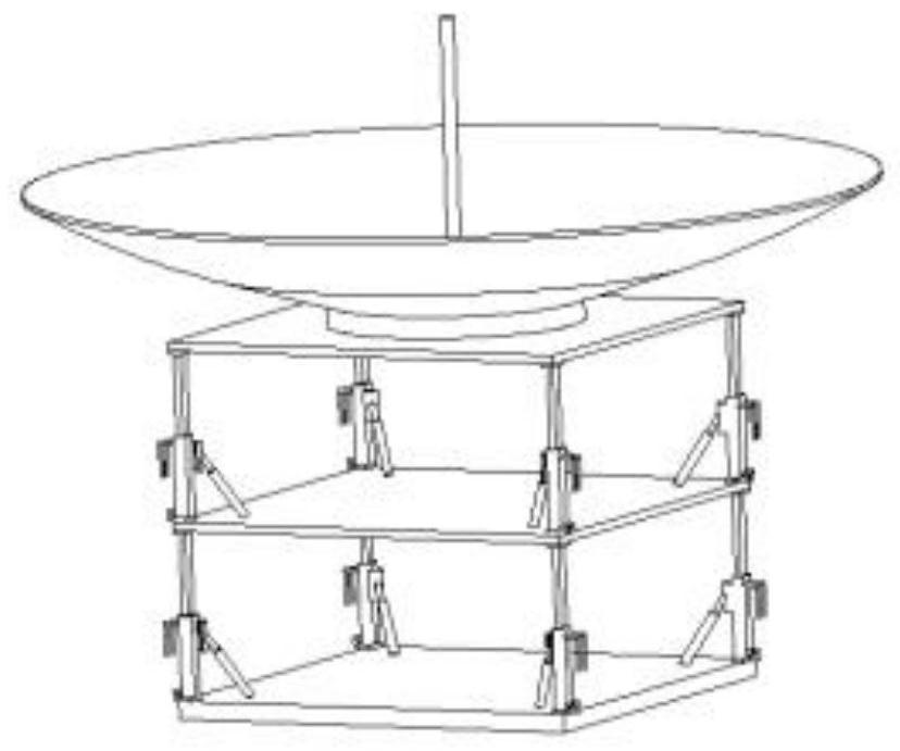
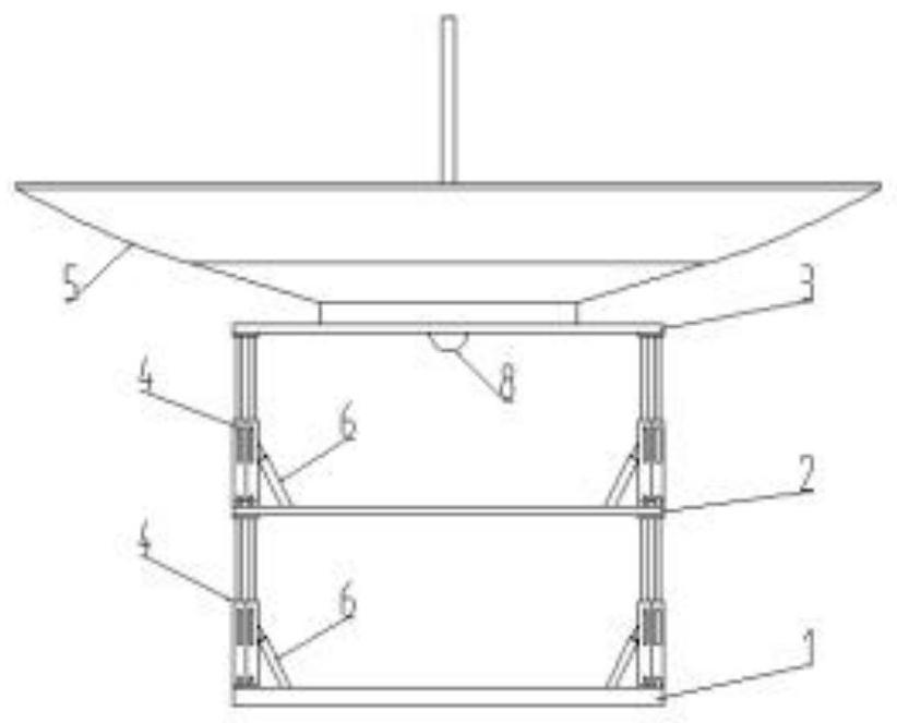
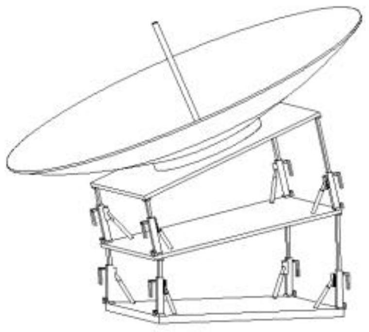
[0032] A large-scale combined inclined platform antenna, which abandons the traditional azimuth and elevation antenna base, and adopts the form of multiple groups of platforms connected in series. The relative tilting movement at a certain angle is realized through the servo mechanism between adjacent platforms, and the multi-layer combination realizes the large-angle tilting of...


PUM


Abstract

The invention discloses a combined inclined platform type large antenna, and belongs to the technical field of antennas. The antenna comprises a reflector and an antenna seat frame. The antenna seat frame is composed of multiple layers of platforms which are sequentially connected from top to bottom, and the reflector is located on a platform plate of the topmost platform. Each platform comprises supporting columns and a platform plate. The tops of the supporting columns are connected with the platform plate, and the bottoms of the supporting columns are fixed to the next stage of platform plate through lifting devices. Each layer of platform realizes inclined movement in a certain space angle range through the combined movement of the supporting columns at the lower layer. Through the combined movement among the multiple layers of platforms, large-range spatial orientation of the reflector is finally realized. The antenna can realize an overhead tracking function, and has the characteristics of simple structure, reliable transmission, convenience in construction and the like.

Description

technical field [0001] The invention relates to the technical field of antennas, in particular to a large-scale combined inclined platform antenna. Background technique [0002] Antennas of satellite ground fixed tracking and measurement stations often use azimuth-elevation antenna mounts. This type of mount has the advantages of simple structure, traditional reliability, and high precision. But it can't solve the problem of overhead tracking. Overhead tracking is a key technique in moving target tracking. Especially for low-orbit satellites, there will be a "blind zone" near the 90° zenith. When the satellite flies through this blind area, the azimuth velocity of the antenna changes sharply while the pitch velocity changes slowly, and the antenna of the ground station will lose the tracking target because the azimuth velocity is not high enough. The size of the "blind zone" is related to the azimuth velocity of the ground station antenna and the target height. Increasi...

Claims


Application Information

Patent Timeline
IPC IPC(8): H01Q1/32H01Q1/22
CPCH01Q1/12H01Q3/02
Inventor 曹江涛宫玉松韦俊苓王大为张晓冲肖松张济良董培松孙琪常硕赵增芳
Owner NO 54 INST OF CHINA ELECTRONICS SCI & TECH GRP
Why Eureka
Try Eureka