
Transmission lens with phase and amplitude independently regulated and controlled and transmission array antenna

A lens and amplitude technology, applied in antennas, antenna arrays, electrical components, etc., can solve the problems of low sidelobe and strong focusing performance, cannot fully meet the high gain of transmission array antenna, lack of independence and flexibility of amplitude control, etc. Achieve the effects of low side lobe level, strong focus and high gain

Inactive Publication Date: 2021-11-23
BEIJING INSTITUTE OF TECHNOLOGYGY
View PDF6 Cites 2 Cited by
  • Summary
  • Abstract
  • Description
  • Claims
  • Application Information

AI Technical Summary

Problems solved by technology

These methods rely on additional power division network design or transmission phase distribution, lack the independence and flexibility of amplitude control, and cannot fully meet the requirements of high gain, low sidelobe and strong focusing performance of transmission array antennas

Method used


Image

  • Transmission lens with phase and amplitude independently regulated and controlled and transmission array antenna
  • Transmission lens with phase and amplitude independently regulated and controlled and transmission array antenna
  • Transmission lens with phase and amplitude independently regulated and controlled and transmission array antenna

Examples


Embodiment Construction

[0026] The present invention will be described in detail below with reference to the accompanying drawings and examples.

[0027] The invention provides a transmission lens and a transmission array antenna with independently adjustable phase and amplitude. By adjusting the structural parameters of the middle layer of the array unit, 360° phase full coverage can be achieved. The layer structure realizes the control of the transmission amplitude, and finally achieves the performance of the transmission antenna with significantly increased gain, reduced sidelobe level, and high transmission characteristics and strong focus.

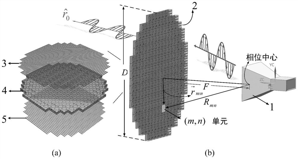
[0028] like figure 1 (a), shown in (b), transmission array antenna of the present invention is by a standard HD-100SGAH10 horn antenna as feed source, and its gain is 10dBi, and operating frequency band is 10GHz, and a metasurface lens ( That is, the transmission lens), the phase center of the feed horn is located at the focal point of the lens. The metasu...


PUM

PropertyMeasurementUnit
Lengthaaaaaaaaaa
Widthaaaaaaaaaa
Widthaaaaaaaaaa

Abstract

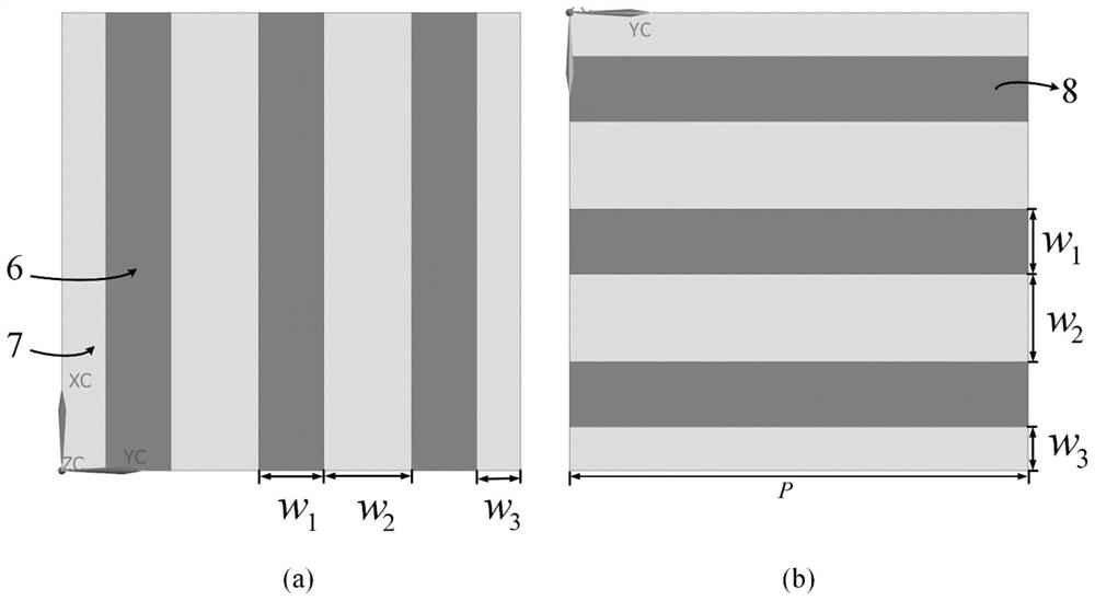
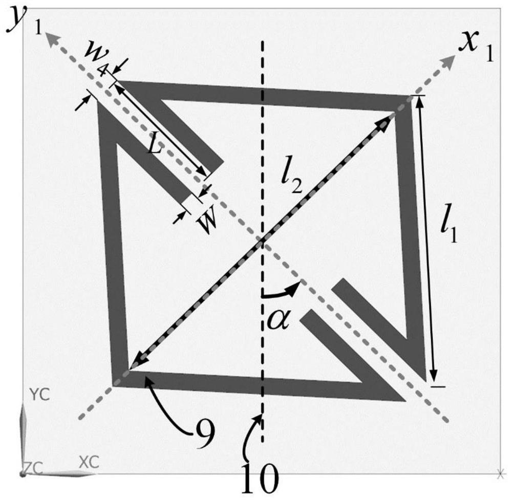
The invention discloses a transmission lens with phase and amplitude independently regulated and controlled and a transmission array antenna. The transmission lens comprises a feed source and a transmission lens, the phase center of the feed source is located on the focus of the transmission lens, and the transmission lens comprises a plurality of periodically arranged metasurface lens units. Each metasurface lens unit comprises an upper metal patch, a middle metal patch, a lower metal patch and two dielectric plates between the patches; the upper metal patch and the lower metal patch are respectively three metal grids which are arranged in parallel, the upper-layer metal grid and the lower-layer metal grid are perpendicular to each other, the width of the upper-layer metal grid and the length of the lower-layer metal grid are both w1, the length of the upper-layer metal grid and the length of the lower-layer metal grid are both P, and the distance between the metal grids is both w2; the middle metal patch is a rhombic ring which is formed by metal strips in a surrounding manner and is provided with an acute-angle vertex angle opening, and the two pairs of metal strips parallel to a diagonal line extend from the opening to the center of the rhombic ring. According to the invention, the independent control of the transmission phase and amplitude can be realized, and the requirements of high gain, low side lobe and strong focusing performance of the transmission array antenna are met.

Description

technical field [0001] The invention belongs to the technical field of transmission array antenna design, and in particular relates to a transmission lens and a transmission array antenna whose phase and amplitude are independently regulated. Background technique [0002] Transmitarray antenna (TA) is a high-gain antenna. Due to its significant advantages such as high gain, flat structure, light weight, low cost, and no feed-blocking, it has received more and more attention in recent years. Therefore, transmissive array antennas are often used in long-range systems such as satellite ground links, mobile communication systems, and radar systems. [0003] For this reason, the design of the transmission array antenna is also constantly developing. In order to achieve high gain, the existing design of the transmission array antenna usually adopts multi-layer frequency selective surface structure cascaded to achieve 360° phase range coverage to meet the requirements of the transm...

Claims


Application Information

Patent Timeline
IPC IPC(8): H01Q15/02H01Q21/00
CPCH01Q15/02H01Q21/00
Inventor 金城尹丽媛
Owner BEIJING INSTITUTE OF TECHNOLOGYGY
Learn More