BUCK-BOOST with high-precision low-ripple light-load working mode

A working mode, low-ripple technology, applied in conversion equipment without intermediate conversion to AC, output power conversion devices, instruments, etc., can solve the problems of slow loop response time, large VOUT voltage ripple, etc., to reduce Voltage ripple, low energy effect

Active Publication Date: 2021-11-23
SOUTHCHIP SEMICON TECH SHANGHAI CO LTD
View PDF5 Cites 1 Cited by
  • Summary
  • Abstract
  • Description
  • Claims
  • Application Information

AI Technical Summary

Problems solved by technology

[0009] Aiming at the above problems, the present invention proposes a BUCK-BOOST with high-precision, low-ripple and light-load working mode. The main problem of the above-mentioned traditional method is that the power stage is allowed to work in the intermittent mode by monitoring the real-time voltage value of Vc. The response time of the circuit is slow, VOUT will have a large voltage ripple, and the DC value of VOUT will also vary with VIN, VOUT and load

Method used


Image

  • BUCK-BOOST with high-precision low-ripple light-load working mode
  • BUCK-BOOST with high-precision low-ripple light-load working mode
  • BUCK-BOOST with high-precision low-ripple light-load working mode

Examples


Embodiment Construction

[0025]The present invention will be described in detail below in conjunction with the accompanying drawings.

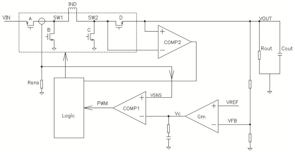
[0026] The system block diagram of the present invention is as Figure 4 shown. The internal reference voltage VREF and VOUT voltage feedback signals are differentially amplified to generate a voltage control signal Vc, and Vc is converted by V / I to generate a current control signal IC and IPFM. There is a clamping circuit on the IC signal path. When the output current of V / I conversion is greater than the value set by the clamping circuit, IC is equal to the output current of V / I conversion. When the output current of V / I conversion is less than the value set by the clamp circuit, IC is equal to the set value. The comparator COMP1 compares the inductor current sampling signal ISNS with IC to generate a pulse width modulation signal PWM. TPFM is a current control delay circuit, the delay time increases with the decrease of IPFM, and a signal pulse T3 is generated a...


PUM


Abstract

The invention belongs to the technical field of analog circuits, and particularly relates to a BUCK-BOOST with a high-precision low-ripple light-load working mode. According to the scheme, an intermittent working mode is replaced by a monopulse mode, and in a light load mode, the power level only works for one cycle each time, so that voltage ripples can be reduced; the Vc signal is used for modulating the interval time of the monopulse mode, and the lighter the load is, the longer the interval time is. The purpose is that the working frequency of the power level is linearly reduced along with the load, and the audio frequency can be entered only when the load is very light. And meanwhile, as only one cycle is operated each time, the transmitted energy is small, and the audio noise is far lower than the noise of the scheme shown in the figure 3. The system modulates the interval time by using the average value of the Vc, and can ensure that the voltage precision of the VOUT does not change along with the VIN, the VOUT and the load.

Description

technical field [0001] The invention belongs to the technical field of analog circuits, and in particular relates to a BUCK-BOOST with a high-precision, low-ripple and light-load working mode. Background technique [0002] BUCK-BOOST is the abbreviation of inductive switch buck-boost DCDC voltage regulator. Its basic principle is as figure 1 shown. MOS switches ABCD and inductors form the power stage circuit. The control circuit allows ABCD to work alternately according to a certain timing. While keeping the output voltage VOUT constant, the inductance of the energy storage element is used to transfer the energy from the input VIN to the output VOUT. [0003] When VIN>>VOUT, switch D is always on and C is always off, and switch AB is alternately on and off. The system works in a simple step-down mode (BUCK mode). When VIN<<VOUT, switch A is always on and B is always off, and switch CD is alternately on and off. The system works in a simple boost mode (BOOST...

Claims


Application Information

Patent Timeline
Patent Type & Authority Applications(China)
IPC IPC(8): H02M3/158H02M3/04H02M1/14
CPCH02M3/1582H02M3/04H02M1/14
Inventor 解建章
Owner SOUTHCHIP SEMICON TECH SHANGHAI CO LTD
Why Eureka
Try Eureka