Eureka AIR delivers breakthrough ideas for toughest innovation challenges, trusted by R&D personnel around the world.

CNC machining center capable of improving product quality

A machining center and product quality technology, applied in metal processing equipment, metal processing machinery parts, manufacturing tools, etc., can solve the problems of low production efficiency, single style, and few types, so as to achieve output improvement, quality improvement, and avoid deviation Effect

Pending Publication Date: 2021-11-26
苏州聚屹盛精密机械有限公司
View PDF0 Cites 1 Cited by
  • Summary
  • Abstract
  • Description
  • Claims
  • Application Information

AI Technical Summary

Problems solved by technology

[0004] Most of the existing CNC machining centers that improve product quality have few types and single styles, and most of them are directly fixed by the base, and the objects may be offset, which makes the quality of the produced products slightly lower. It is troublesome to replace the milling cutter and boring cutter, and the production efficiency is low

Method used


Image

  • CNC machining center capable of improving product quality
  • CNC machining center capable of improving product quality
  • CNC machining center capable of improving product quality

Examples


Embodiment 1

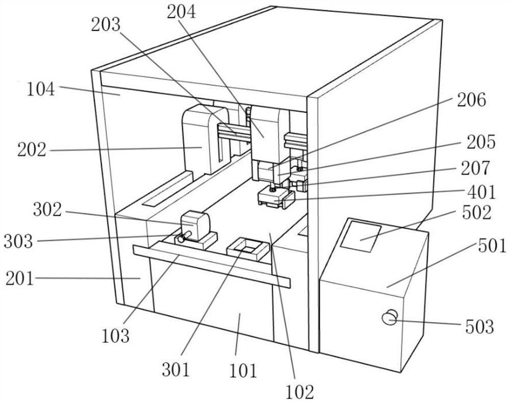
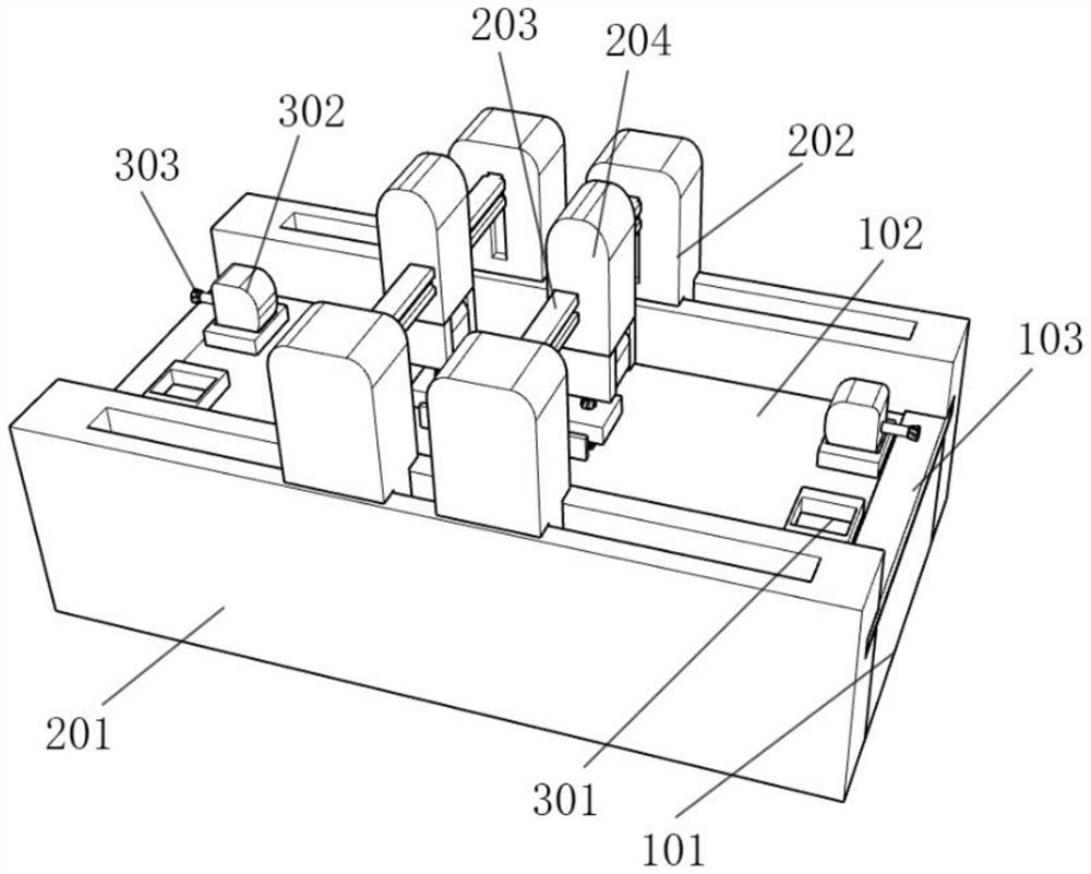
[0027] The present invention provides a kind of CNC processing center that improves product quality, with reference to figure 1 , including a main body mechanism 1, a cutting and grinding mechanism 2, and a control mechanism 5, and also has: the main body mechanism 1 includes a bottom box 101, a bottom plate 102, an edge fixing plate 103, and a casing 104;

[0028] Cutting and grinding mechanism 2: installed at both ends of the main body 1, and fixedly connected with the main body 1;

[0029] Backup mechanism 3: installed on the top of the main mechanism 1, and fixedly connected with the main mechanism 1;

[0030] Fixing mechanism 4: installed on the top of the main body 1, and fixedly connected with the main body 1;

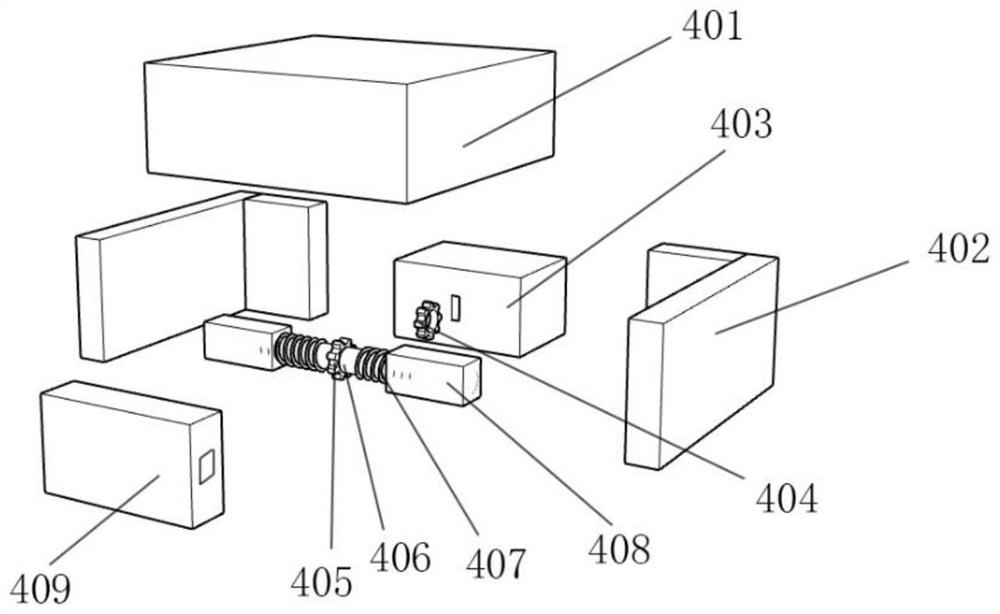
[0031] refer to image 3 Further, the fixing mechanism 4 includes an object to be processed 401, a fixed clamp column 402, a gear box 403, an output gear 404, an auxiliary gear 405, a double-ended column 406, a double-ended thread 407, a fixed double-ended cyl...

Embodiment 2

[0037] refer to Figure 4 Further, the object 401 to be processed is movably connected to the top of the second mechanism 7, the second mechanism 7 includes the second base 701, the second mounting seat 702, the second mounting plate 703, the pneumatic telescopic cylinder 704, the pneumatic telescopic column 705, The gas injection port 706, the object 401 to be processed is movably connected to the top of the second base 701, the top of the bottom plate 102 is fixedly connected with two bases 701 of the second example, and the top of the bottom plate 102 is fixedly connected with four mounting bases 702 of the second example and are located in the second example On both sides of the base 701, the top side of the mounting seat 702 of Example 2 is fixedly connected with the mounting plate 703 of Example 2, and the inner side of the mounting plate 703 of Example 2 is fixedly connected with a pneumatic telescopic tube 704, and the inner side of the pneumatic telescopic tube 704 is ...

Embodiment 3

[0039] refer to Figure 5 , the object to be processed 401 is movably connected to the top of the example 3 mechanism 6, the example 3 mechanism 6 includes the example 3 base 601, the example 3 mounting seat 602, the motor mounting plate 603, the example 3 motor 604, the example 3 output shaft 605, the example 3 thread 606, example three push column 607, the object 401 to be processed is movably connected to the top of the example three base 601, the top of the bottom plate 102 is fixedly connected with two example three bases 601, and the top of the bottom plate 102 is fixedly connected with four example three mounting seats 602 And it is located on both sides of the base 601 of the third example, the top side of the mounting seat 602 of the third example is fixedly connected with the motor mounting plate 603, the side of the motor mounting plate 603 is fixedly connected with the motor 604 of the third example, and the inner top of the motor 604 of the third example is movable...


PUM


Abstract

The invention discloses a CNC machining center capable of improving the product quality. A fixing mechanism comprises an object needing to be processed, a fixed clamping column, a gear box, an output gear, an auxiliary gear, a double-end column, a double-end thread, a fixed double-end cylinder and a gear protection box; the auxiliary gear is fixedly connected to the middle of the side part of the double-end column; the two ends of the side part of the double-end column are fixedly connected with the double-end thread; the fixed double-end cylinder is movably connected with the gear protection box; the top end of the fixed double-end cylinder is fixedly connected with the fixed clamping column; the fixed clamping column is in an L shape; the top of the gear box is movably connected with the object needing to be processed; and the object needing to be processed is fixed through the fixed clamping column, so that when equipment operates to work, the object needing to be processed is prevented from deviating. According to the CNC machining center capable of improving the product quality provided by the invention, the fixing mechanism is adopted to clamp the object needing to be processed , so that the problem that the quality of a finished product is not high due to the fact that the the object needing to be processed deviates is avoided; and the deviation condition can be effectively avoided through fixing of the fixed clamping column, so that the quality of the product is improved.

Description

technical field [0001] The invention relates to the field of numerical control, more specifically, the utility model relates to a CNC machining center for improving product quality. Background technique [0002] CNC is the English abbreviation of CNC milling machine. It is a new processing technology. The main job is to compile processing programs, that is, to convert the original manual work into computer programming. Of course, manual processing experience is required. There are many types of parts that can be processed by CNC machine tools, and the processing efficiency is relatively high. high. [0003] There are still defects in CNC machining centers in the prior art, such as: [0004] Most of the existing CNC machining centers that improve product quality have few types and single styles, and most of them are directly fixed by the base, and the objects may shift, which makes the quality of the produced products slightly lower. It is troublesome to replace the milling...

Claims


Application Information

Patent Timeline
Patent Type & Authority Applications(China)
IPC IPC(8): B23P23/04B23Q1/72B23Q3/06B23Q3/08B23C3/00B23C9/00
CPCB23P23/04B23C3/00B23Q3/06B23Q3/08B23C9/00B23Q1/72
Inventor 杨秀晨
Owner 苏州聚屹盛精密机械有限公司
Why Eureka
Eureka Blog
Learn More