A spring-type safety valve with a new type of back pressure adjustment mechanism and its application method
A technology for adjusting mechanisms and safety valves, applied in safety valves, balance valves, valve devices, etc., can solve the problems of large leakage of spring-type safety valves, affecting the sealing performance of safety valves, and slow valve opening speed, so as to improve safety , Improve sealing performance, reduce the effect of large pressure difference between opening and closing
- Summary
- Abstract
- Description
- Claims
- Application Information
AI Technical Summary
Problems solved by technology
Method used
Image
Examples
specific Embodiment approach 1
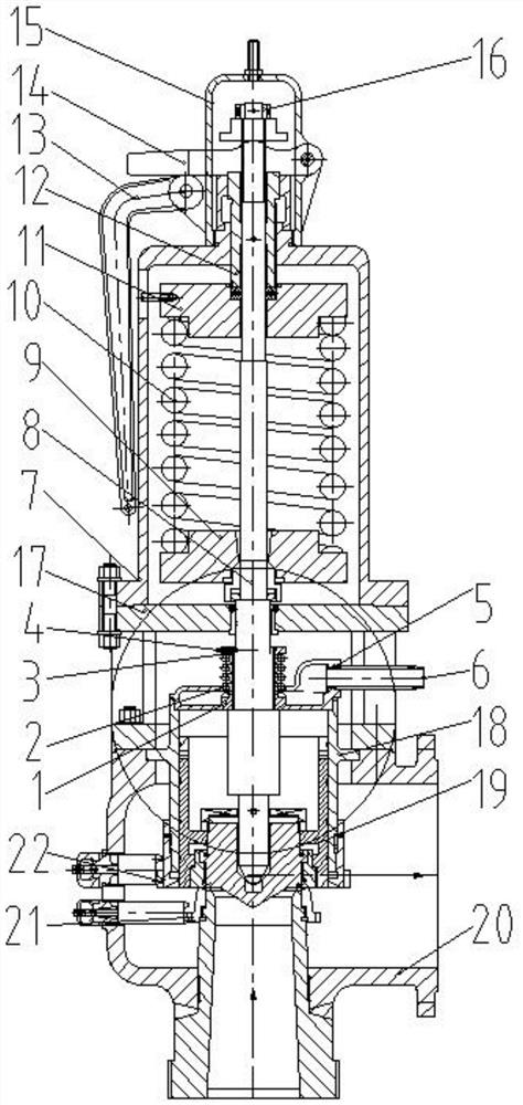
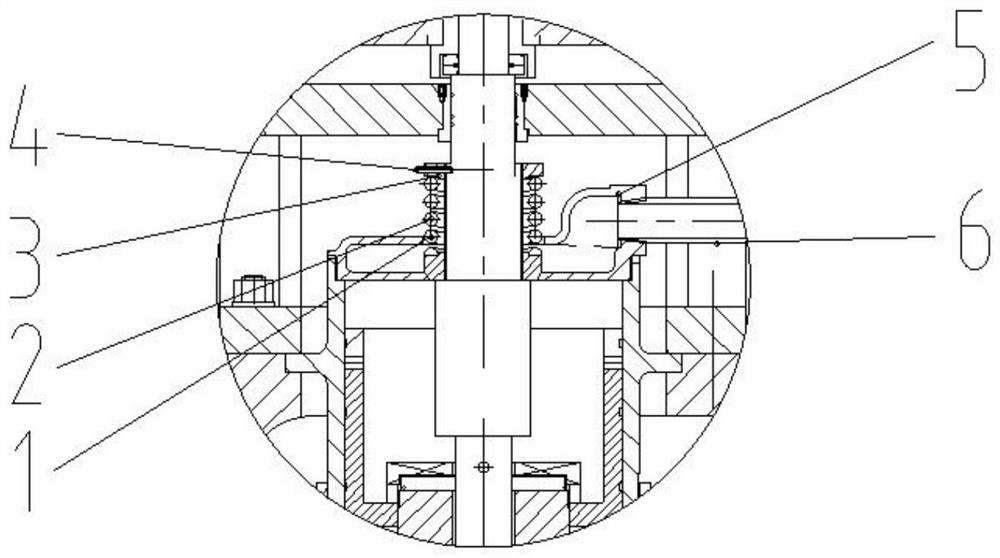
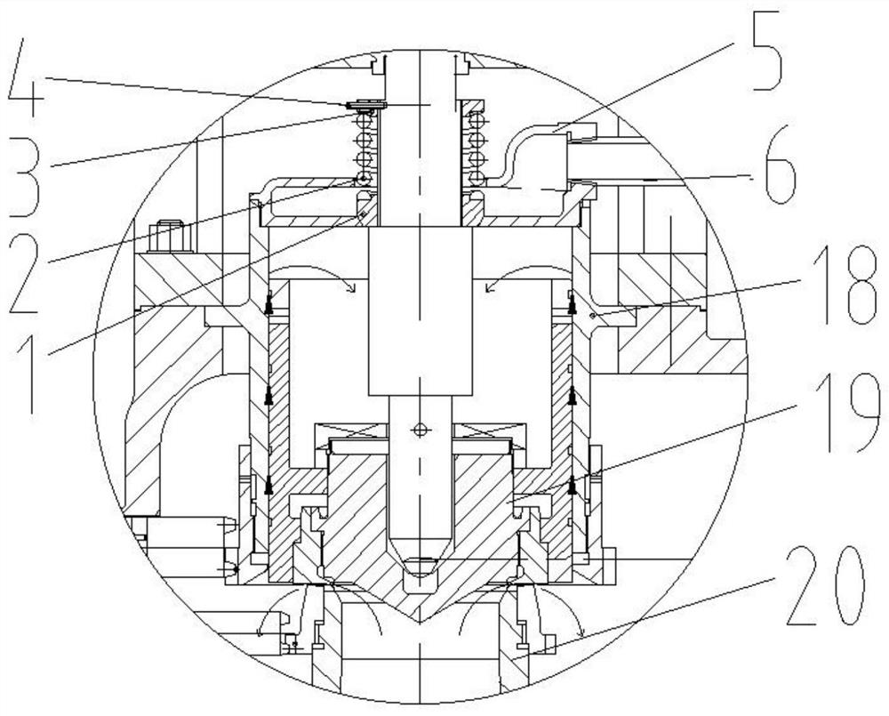
[0039] Specific implementation mode one: combine Figure 1-Figure 6Describe this embodiment, a spring safety valve with a new type of back pressure adjustment structure in this embodiment, including a valve body assembly 20, a cooler 17, and a spring bonnet mechanism, and a valve body assembly 20, a cooler 17, and a spring bonnet mechanism Connected sequentially from bottom to top, the bottom of the valve body assembly 20 is provided with an inlet flow channel, the side end of the valve body assembly 20 is provided with an outlet flow channel, the valve body assembly 20 is provided with a guide sleeve 18 and a valve core 19, and the valve core 19 is arranged on The guide sleeve 18 forms a sealing surface with the inlet channel of the valve body assembly 20. The valve stem 8 passes through the spring bonnet mechanism and the cooler 17 to connect with the valve core 19. The cooler 17 is provided with an exhaust chamber 5 and an exhaust chamber. The pipe 6, the exhaust chamber 5 ...
specific Embodiment approach 2
[0041] Specific implementation mode two: combination Figure 1-Figure 6 Describe this embodiment, a spring safety valve with a new type of back pressure adjustment structure in this embodiment, the spring bonnet mechanism includes a spring cover 7, a lower spring seat 9, a spring 10, an upper spring seat 11, an adjustment screw 12 and The stem nut 16 and the spring cover 7 are arranged on the cooler 17, the spring cover 7 is provided with the lower spring seat 9, the spring 10 and the upper spring seat 11, and the lower spring seat 9, the spring 10 and the upper spring seat 11 are set on the valve in turn. On the stem 8, the valve stem 8 is connected with the spring cover 7 through the adjustment screw 12, the upper spring seat 11 is fixedly connected with the adjustment screw 12, the end of the valve stem 8 is installed with a stem nut 16, and the stem nut 16 is used to control the valve stem 8 moves up and down, the lower spring seat 9, spring 10 and upper spring seat 11 in ...
specific Embodiment approach 3
[0042] Specific implementation mode three: combination Figure 1-Figure 6 Describe this embodiment, a spring safety valve with a new type of back pressure adjustment structure in this embodiment, the spring cover 7 is provided with a small cover 15, a handle 13 and a shift fork 14 are installed on the small cover 15, and the shift fork 14 Set between the adjustment screw 12 and the stem nut 16, the handle 13 is set under the shift fork 14 and contacts with one end of the shift fork 14, on the basis of the second specific embodiment, a small cover 15 is set on the top of the spring cover 7, A handle 13 and a shift fork 14 are hingedly arranged on the small cover 15, and the shift fork 14 is driven by the control handle 13 to move the valve stem 8 up and down, so as to manually control the opening and closing of the safety valve, thereby achieving the effect of pressure relief in the safety valve.
PUM
 Abstract
Description
Claims
Application Information
 - R&D
- Intellectual Property
- Life Sciences
- Materials
- Tech Scout
- Unparalleled Data Quality
- Higher Quality Content
- 60% Fewer Hallucinations
Browse by: Latest US Patents, China's latest patents, Technical Efficacy Thesaurus, Application Domain, Technology Topic, Popular Technical Reports.
© 2025 PatSnap. All rights reserved.Legal|Privacy policy|Modern Slavery Act Transparency Statement|Sitemap|About US| Contact US: help@patsnap.com


