Stirring and sludge scraping system for mechanical acceleration clarification tank and use method of stirring and sludge scraping system

A technology for accelerating clarification and mud systems, applied in separation methods, chemical instruments and methods, sedimentation tanks, etc., can solve problems such as poor stirring effect, incomplete sedimentation and scraping, and achieve the effect of improving sedimentation efficiency.

Inactive Publication Date: 2021-11-30
JIANGSU YIHUAN GROUP
View PDF1 Cites 2 Cited by
  • Summary
  • Abstract
  • Description
  • Claims
  • Application Information

AI Technical Summary

Problems solved by technology

[0004] When the above-mentioned patent is in use, there are many deficiencies. First, the above-mentioned patent is provided with a stirring paddle on the lifting impeller, but the solution area of ​​the clarification tank that the paddle contacts is always in the middle of the clarification tank, and the stirring effect is not good; the second , when the long mud scraper set in the above-mentioned patent scrapes the sediment on the clarifier, the sediment will adhere to the long mud scraper, resulting in incomplete scraping of the sediment inside the clarifier; third, the scraped sediment needs to be discharged , the clarified water can be used for other purposes, after the sediment and water can be separated, the sediment and water can be separated and discharged separately, and part of the water remains in the clarification tank for use

Method used


Image

  • Stirring and sludge scraping system for mechanical acceleration clarification tank and use method of stirring and sludge scraping system
  • Stirring and sludge scraping system for mechanical acceleration clarification tank and use method of stirring and sludge scraping system
  • Stirring and sludge scraping system for mechanical acceleration clarification tank and use method of stirring and sludge scraping system

Examples


Embodiment Construction

[0043] In order to make the purpose, technical solution and advantages of the present invention clearer, the technical solution of the present invention will be clearly and completely described below in conjunction with specific embodiments of the present invention and corresponding drawings. Apparently, the described embodiments are only some of the embodiments of the present invention, but not all of them. Based on the embodiments of the present invention, all other embodiments obtained by persons of ordinary skill in the art without making creative efforts belong to the protection scope of the present invention.

[0044] The technical solutions provided by various embodiments of the present invention will be described in detail below in conjunction with the accompanying drawings.

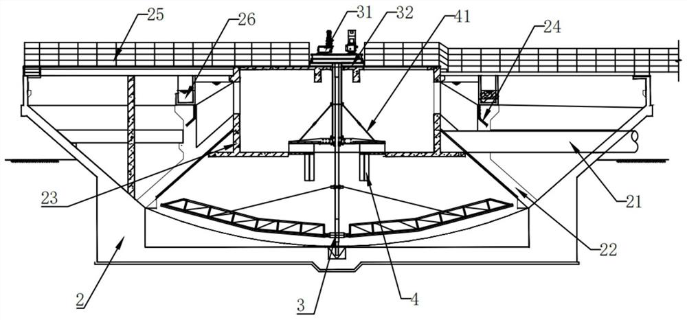
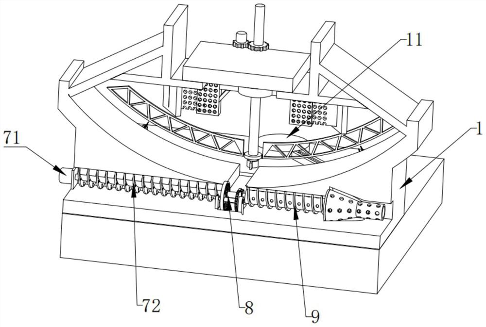
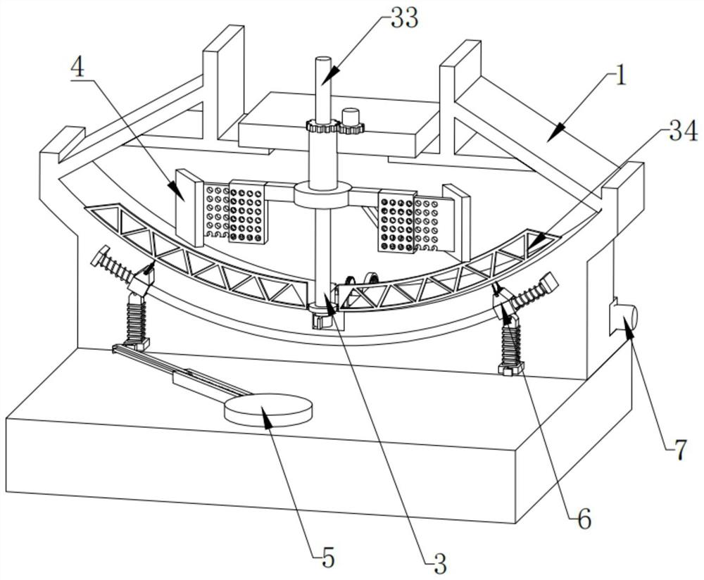
[0045] refer to Figure 1 to Figure 9 As shown, the embodiment of the present invention provides a stirring and scraping system for a mechanically accelerated clarifier, including a tank body 1,...


PUM


Abstract

The invention discloses a stirring and sludge scraping system for a mechanical acceleration clarification tank and a use method of the stirring and sludge scraping system, and belongs to the technical field of sludge treatment. The stirring and sludge scraping system comprises a tank body, a sludge scraping mechanism, a stirring mechanism, a cleaning mechanism and a slag discharging mechanism, the sludge scraping mechanism is rotationally installed on the tank body, the stirring mechanism is installed on the tank body, and the cleaning mechanism is slidably installed on the tank body. The cleaning mechanism comprises a driving mechanism and two cleaning assemblies, the driving mechanism is installed on the tank body, the two cleaning assemblies are both installed on the driving mechanism in a sliding mode, and the slag discharging mechanism is rotatably installed on the tank body. According to the stirring and sludge scraping system for the mechanical acceleration clarification tank and the use method of the stirring and sludge scraping system, sediments generated in the clarification tank are scraped, meanwhile, the sediments left on the sludge scraping mechanism are cleaned, then water and the sediments are discharged separately, and the invention further provides the use method of the sludge scraping mechanism.

Description

technical field [0001] The invention relates to the technical field of sludge treatment, in particular to a stirring and scraping mud system for a mechanically accelerated clarifier and a use method thereof. Background technique [0002] The clarifier is a water purification structure integrating coagulation, reaction and sedimentation. It is one of the most common treatment facilities in water treatment. Classification: The clarifier can be divided into two types: sludge suspension clarifier and sludge circulation clarifier. The sludge suspension clarifier is divided into suspension and pulse clarifiers; the sludge circulation clarifier is divided into mechanical acceleration and hydraulic circulation clarifiers. [0003] The existing Chinese patent with the publication number CN205699620U discloses a mechanically accelerated clarifier agitating mud scraper for environmental protection. This utility model discloses a mechanically accelerated clarifier agitating mud scraper...

Claims


Application Information

Patent Timeline
Patent Type & Authority Applications(China)
IPC IPC(8): B01D21/01B01D21/06B01D21/28B01D21/00
CPCB01D21/01B01D21/28B01D21/06B01D21/0012B01D21/00
Inventor 殷益明杭俊亮杭乾频祝磊杨超
Owner JIANGSU YIHUAN GROUP
Why Eureka
Try Eureka