Separation equipment for gas purification
A technology for separation equipment and gas purification, applied in separation methods, dispersion particle separation, chemical instruments and methods, etc., can solve problems such as increased labor costs, environmental pollution, and difficult cleaning of impurities, so as to achieve the effect of accelerating purification and avoid cleaning times , Ease of maintenance
- Summary
- Abstract
- Description
- Claims
- Application Information
AI Technical Summary
Problems solved by technology
Method used
Image

Examples
Embodiment 1
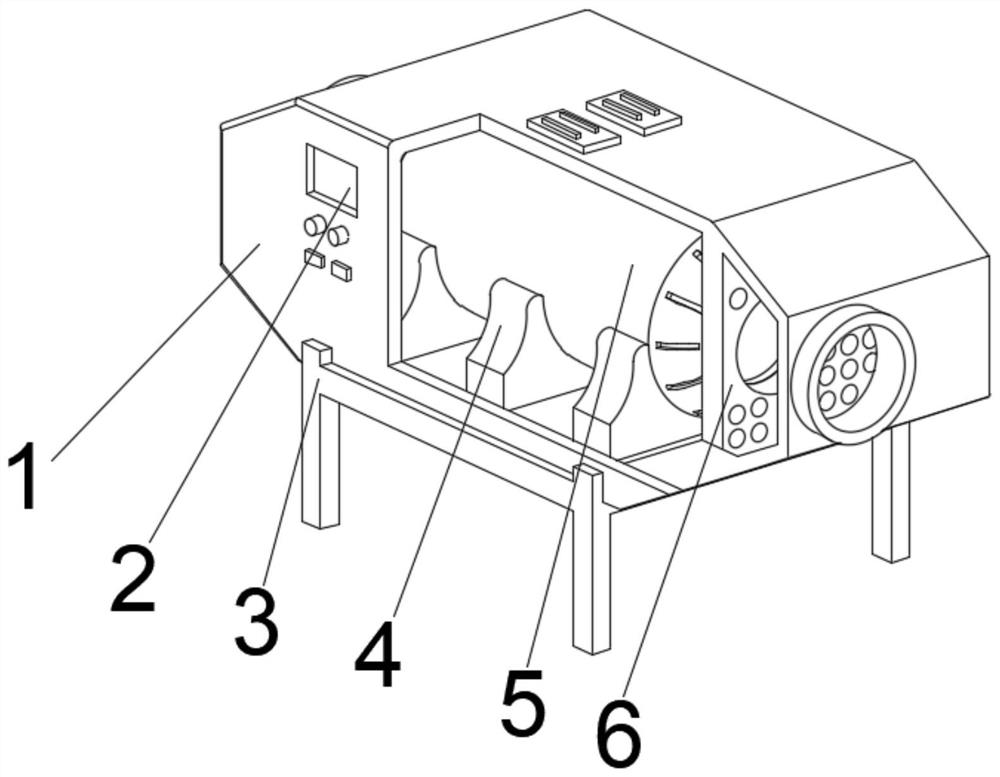
[0033] see Figure 1-2 , the present invention provides a technical solution: a separation device for gas purification, comprising a main body 1, fixed brackets 3 are fixedly connected to both sides of the bottom of the main body 1, a control panel 2 is fixedly connected to the top left side of the front of the main body 1, the main body 1 is fixedly connected with a fixed base 4 in the middle of the bottom of the inner cavity, and the middle position of the top of the fixed base 4 is fixedly connected with a separation device 5 .
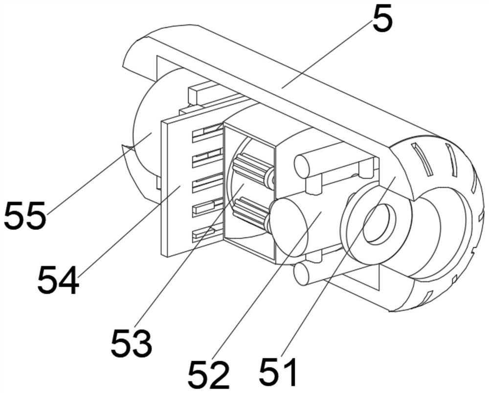
[0034] Wherein, the separation device 5 comprises a separation tank 51, a pre-cooler 52 is arranged in the middle part of the inner wall of the right side of the separation tank 51, and a filter mechanism 53 is arranged in the middle part of the left outer wall of the pre-cooler 52, and the inner chamber bottom of the separation tank 51 is located at the filter mechanism The left side of 53 is fixedly connected with a continuous separator 54, and t...
Embodiment 2
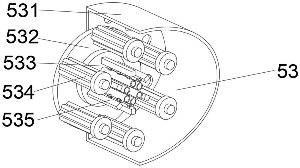
[0037] see Figure 1-4 , On the basis of Embodiment 1, the present invention provides a technical solution: component 1 of the filter mechanism 53 includes a filter housing 531, a sealing plate 532 is provided in the middle of the left inner wall of the filter housing 531, and a sealing plate 532 is provided in the middle of the right outer wall of the sealing plate 532. Fixedly connected with a positioning guide frame 533, the right side of the sealing plate 533 is located at both sides of the positioning guide frame 533 and fixedly connected with a multi-stage separation filter 534, and the side of the positioning guide frame 533 near the multi-stage separation filter 534 is provided with a swing filter Piece 535.
[0038] Among them, the first component of the collection mechanism 55 includes a collection pipe 551, the left end of the collection pipe 551 is provided with a collection box 554, the right inner wall of the collection box 554 is fixedly connected with a protect...
Embodiment 3
[0041] see Figure 1-6 , on the basis of Embodiment 1 and Embodiment 2, the present invention provides a technical solution: component 2 of the filter mechanism 53 includes an adsorption column d1, the inner walls of both sides of the adsorption column d1 are provided with adsorption modules d2, and the adsorption modules d2 are far away from the adsorption One side of the column d1 is fixedly connected with the rotating shaft d5, the middle of both sides of the adsorption module d2 close to the rotating shaft d5 is fixedly connected with the extruding plate d3, and the side of the adsorption module d2 close to the adsorption column d1 is provided with an automatic adjustment plate d4.
[0042] Wherein, the second component of the collection mechanism 55 includes a shell t1, the middle position of the inner cavity bottom of the shell t1 is fixedly connected with a force plate t2, the top of the force plate t2 is provided with a collector t3, and the middle part of the inner wal...
PUM
 Abstract
Description
Claims
Application Information
 - R&D
- Intellectual Property
- Life Sciences
- Materials
- Tech Scout
- Unparalleled Data Quality
- Higher Quality Content
- 60% Fewer Hallucinations
Browse by: Latest US Patents, China's latest patents, Technical Efficacy Thesaurus, Application Domain, Technology Topic, Popular Technical Reports.
© 2025 PatSnap. All rights reserved.Legal|Privacy policy|Modern Slavery Act Transparency Statement|Sitemap|About US| Contact US: help@patsnap.com