A device and method for in-situ lateral movement of a ship's caudal fin structure

A technology of ships and stern fins, which is applied in the field of ship stern fin structure in situ traversing and floating devices, which can solve the problems that the dock space cannot be fully utilized, and achieves the advantages of easy disassembly and maintenance, small storage area, and improved use efficiency Effect

Active Publication Date: 2022-08-02
HUDONG ZHONGHUA SHIPBUILDINGGROUP
View PDF7 Cites 0 Cited by
  • Summary
  • Abstract
  • Description
  • Claims
  • Application Information

AI Technical Summary

Problems solved by technology

[0003] Therefore, when arranging the docks in the dock, there will be great limitations for this type of ship, resulting in the inability to fully utilize the valuable dock space

Method used


Image

  • A device and method for in-situ lateral movement of a ship's caudal fin structure
  • A device and method for in-situ lateral movement of a ship's caudal fin structure
  • A device and method for in-situ lateral movement of a ship's caudal fin structure

Examples


Embodiment 1

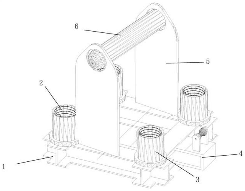
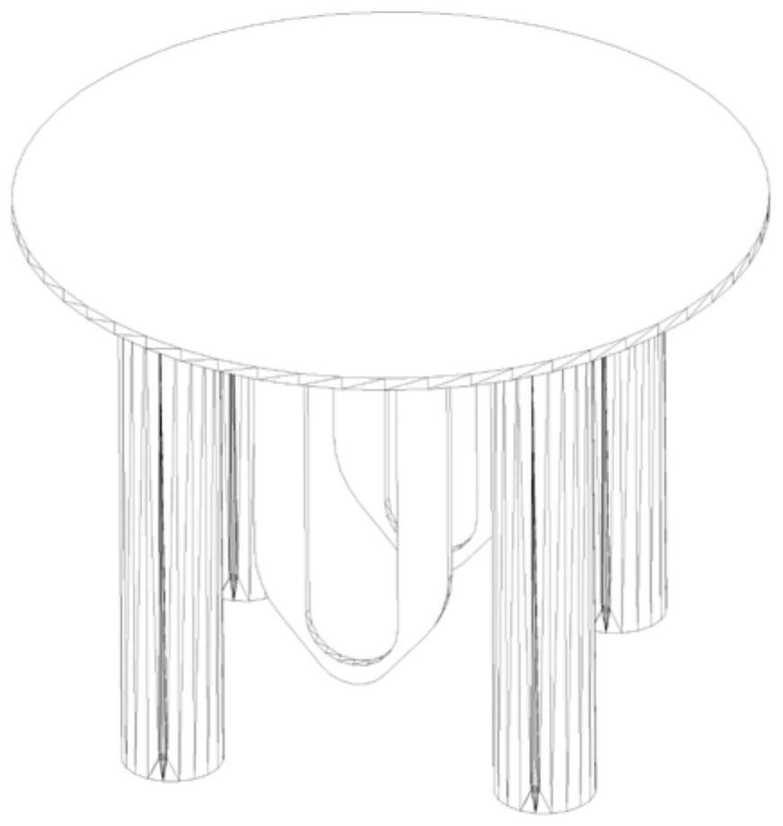
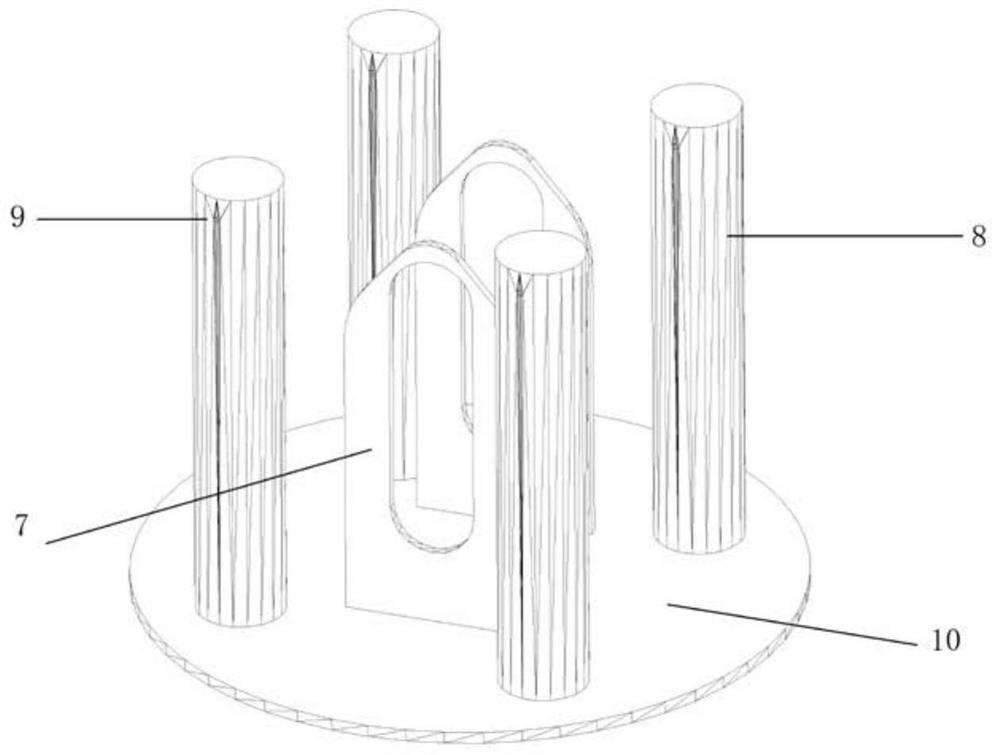
[0034] This embodiment provides an in-situ lateral movement and floating device for a ship's tail fin structure, which includes a lower support structure, an upper support structure and a high support pipe 14, and the lower support structure includes a support base 1, a fixed sleeve 3, a fixed eye plate 5 and a base The fixed pulley 4, the support base 1 is rectangular, the fixed sleeve 3 is installed on the four corners of the support base 1, the top support spring 2 is arranged inside the fixed sleeve 3, and the fixed eye plate 5 is installed on the opposite side of the support base 1. On both sides, the fixing eye plate 5 is provided with positioning holes, and the positioning holes are provided with connecting pins. The upper support structure includes a support pipe base 10, a fixed pipe column, and a guide eye plate 7. The fixed pipe column and the guide eye plate 7 are welded to the bottom of the support pipe base 10. The fixed pipe column matches the fixed sleeve 3, and...

Embodiment 2

[0036] The present embodiment provides a method for in-situ lateral movement and buoyancy of a ship caudal fin structure, including the following steps:

[0037] Step 1. Before the ship's tail fin structure is mounted, set the in-situ traverse floating device on the support position of the stern, weld the support base 1 on the embedded part of the dock ground, and embed the fixed pipe string 8 on the support pipe base 10. into the fixed sleeve 3, through the fixed eye plate 5 and the guide eye plate 7 through the connecting shaft pin 6. At this time, due to the force of the top support spring, the support pipe base 10 and the fixed pipe column 8 are in a suspended state.

[0038] Step 2: Ballast the 5-ton ballast iron on the base of the support pipe to make the entire traverse floating device in a compressed state, and use a pin to pass through the locking pin hole 9 on the side of the fixed pipe string 8 and the fixed sleeve 3, so that the whole The jacking spring is kept in...


PUM


Abstract

The invention provides a device and a method for in-situ lateral movement and buoyancy of a ship tail fin structure. The device includes a lower support structure, an upper support structure and a high support pipe. The lower support structure includes a support base, a fixed sleeve and a fixed eye plate. And the base fixed pulley, the fixed sleeve is installed on the four end corners of the support base, the inside of the fixed sleeve is provided with a top support spring, the fixed eye plate is provided with a positioning hole, and the positioning hole is provided with Connecting pins, the upper support structure includes a support pipe base, a fixed pipe column, and a guide eye plate, the fixed pipe column and the guide eye plate are welded to the bottom of the support pipe base, and the fixed pipe column is matched with the fixed sleeve , the guide eye plate is provided with a long waist hole, the guide eye plate is matched with the fixed eye plate, and the high support pipe is welded on the support pipe base. The invention solves the problem that the ship with the caudal fin structure cannot be moved laterally out of the dock after being floated due to the high support, thereby releasing the limitation of the arrangement of this type of ship in the dock.

Description

technical field [0001] The invention relates to the technical field of ship construction, in particular to a device and method for in-situ lateral movement and floating of a caudal fin structure of a ship. Background technique [0002] In the process of ship construction, the lifting of the ship is an indispensable step after the product is built. Due to its special structural characteristics, a ship with a tail fin structure needs to be provided with multiple high supports in the 50-meter-long area of ​​the stern. Ensure that the caudal fin structure will not sink and deform. Since the top of the high support is higher than the outer plate of the tail fin after the ship floats, the propeller blades, rudder blades, etc., so the ship must complete a longitudinal movement of 50-70 meters in the dock before docking to ensure the top of the high support. Other dynamic displacements that will not collide with the hull and then un-dock. [0003] Therefore, when arranging the doc...

Claims


Application Information

Patent Timeline
Patent Type & Authority Patents(China)
IPC IPC(8): B63C3/00B63C5/04
CPCB63C3/00B63C5/04
Inventor 邵志杰柯金王中海李轶科
Owner HUDONG ZHONGHUA SHIPBUILDINGGROUP
Why Eureka
Try Eureka