
Synchronous winding equipment for back-twist copper foil wires and application method thereof

A copper foil wire and twist-back technology, which is applied in the field of copper foil wire, can solve the problems of copper foil wire breakage, affecting the quality of copper foil wire winding products, and twisting copper foil wire, so as to reduce the twist and improve the winding. The effect of production quality

Pending Publication Date: 2021-11-30
东莞市正润电业科技有限公司
View PDF7 Cites 1 Cited by
  • Summary
  • Abstract
  • Description
  • Claims
  • Application Information

AI Technical Summary

Problems solved by technology

[0003] The traditional copper foil wire will generate stress during the winding and winding process, which will cause twisting of the wound copper foil wire, which will greatly affect the quality of the copper foil wire rewinding product. If the stress is too large, it will even There is a phenomenon of copper foil wire breakage

Method used


Image

  • Synchronous winding equipment for back-twist copper foil wires and application method thereof
  • Synchronous winding equipment for back-twist copper foil wires and application method thereof
  • Synchronous winding equipment for back-twist copper foil wires and application method thereof

Examples


Embodiment

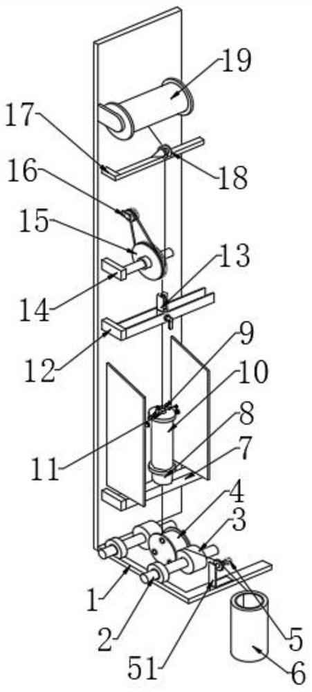
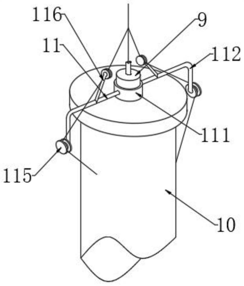
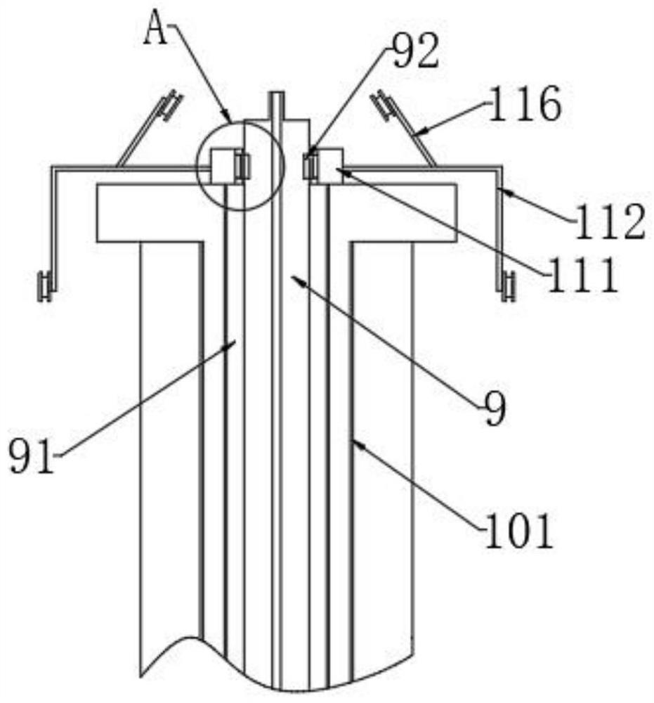
[0048] see Figure 1-3 , a synchronous winding device for untwisted copper foil wires, comprising an installation base main body 1, a pair of driving roller shafts 2 are rotatably connected to the lower end of the installation base main body 1, and engagement wheels are fixedly connected to the outer rotating shaft surfaces of the pair of driving roller shafts 2 3. The inner side of the two engaging wheels 3 is matched to clamp the crimping rotor 4, and the lower end of the installation base body 1 is fixedly connected with the cable clamp assembly 5, which is located on the outside of the engagement wheel 3, and the installation base body 1 Platinum wire 6 is provided on the outer side of the body, and the platinum wire 6 is in contact with the clamp assembly 5. The platinum wire 6 surrounds the outer circumferential surface of the crimping rotor 4, and the front of the installation base main body 1 is fixedly connected with the first connecting base. 7. The upper end of the ...


PUM


Abstract

The invention discloses synchronous winding equipment for back-twist copper foil wires and an application method thereof, and belongs to the field of copper foil wires. According to the synchronous winding equipment for the back-twist copper foil wires and the application method thereof, a back-twist assembly is matched with a three-groove connection main wheel and a three-groove connection auxiliary wheel to reduce the stress generated in the wrapping process of the wrapped copper foil wires, so that the twisting phenomenon of the copper foil wires is reduced, and the winding quality of the copper foil wires is improved; heat generated by friction is conducted to a sleeving ring through an L-shaped connection rod and a guide connection rod, so that a deformation memory metal ring is heated to deform; the deformed deformation memory metal ring is embedded into an embedding groove, so that the guide assembly is limited and fixed; centrifugal force can be generated in the rotating process of the guide assembly, so that the guide assembly is slowly separated from a hollow pipe along with the passing of the rotating time; and the guide assembly is limited and fixed, so that the possibility that the guide assembly is separated from the hollow pipe is reduced, and the stability of the copper wire wrapping process is improved.

Description

technical field [0001] The invention relates to the field of copper foil wires, and more specifically relates to a synchronous winding device for untwisted copper foil wires and a method for using the same. Background technique [0002] A conductor composed of one or several elements twisted together, each element is composed of one or several thin metal strips helically wrapped around the fiber wire and supported by the fiber wire, usually depending on the type of ribbon metal wire Can be divided into: tin-plated copper foil wire; tin-plated alloy copper foil wire; silver-plated copper foil wire; silver-plated alloy copper foil wire; Fiber copper foil wire, sometimes in order to increase the strength, you can replace the polyester fiber in the middle with bulletproof wire, the elasticity, softness and bending strength of the copper foil wire are good; the middle part of the copper foil wire bears longitudinal tension, therefore, the copper foil wire The swing and bend perf...

Claims


Application Information

Patent Timeline
Patent Type & Authority Applications(China)
IPC IPC(8): B65H54/40B65H59/10B65H57/14
CPCB65H54/40B65H59/10B65H57/14
Inventor 李前军
Owner 东莞市正润电业科技有限公司
Learn More