
Combined truss node structure, bridge and construction method

A technology of combining trusses and nodes, applied in truss bridges, erecting/assembling bridges, bridges, etc., can solve problems such as affecting economic effects, driving up construction costs, and easy damage to junction plates, ensuring connection stability and reducing construction difficulty. , the effect of improving the connection strength

Active Publication Date: 2021-11-30
CCCC SECOND HIGHWAY CONSULTANTS CO LTD
View PDF17 Cites 0 Cited by
  • Summary
  • Abstract
  • Description
  • Claims
  • Application Information

AI Technical Summary

Problems solved by technology

[0003] However, due to the difference in stress and deformation properties between concrete and steel, the mechanical properties and stress state of the combined joints of steel web members and concrete inner chords are more complicated, resulting in the gusset plate being easily damaged
At present, in order to maintain the mechanical performance of the structure, many shear keys are arranged in the joint structure of the steel-concrete truss, which makes it difficult to connect the steel web member and the concrete chord member of the roof and floor
At the same time, the assembly of more parts not only increases the workload of node structure processing, but also increases the difficulty of controlling the installation accuracy of the entire node, which pushes up the construction cost and affects the economic effect.

Method used


Image

  • Combined truss node structure, bridge and construction method
  • Combined truss node structure, bridge and construction method
  • Combined truss node structure, bridge and construction method

Examples


Embodiment 1

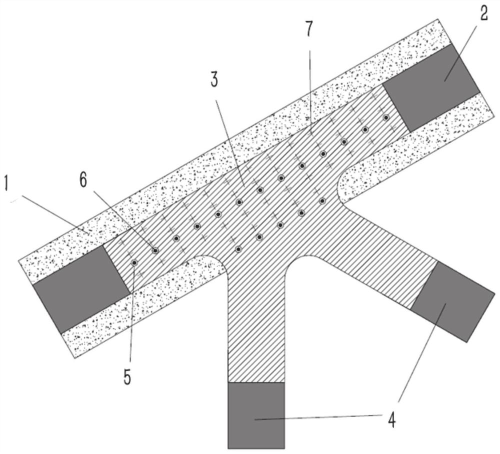
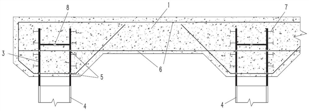
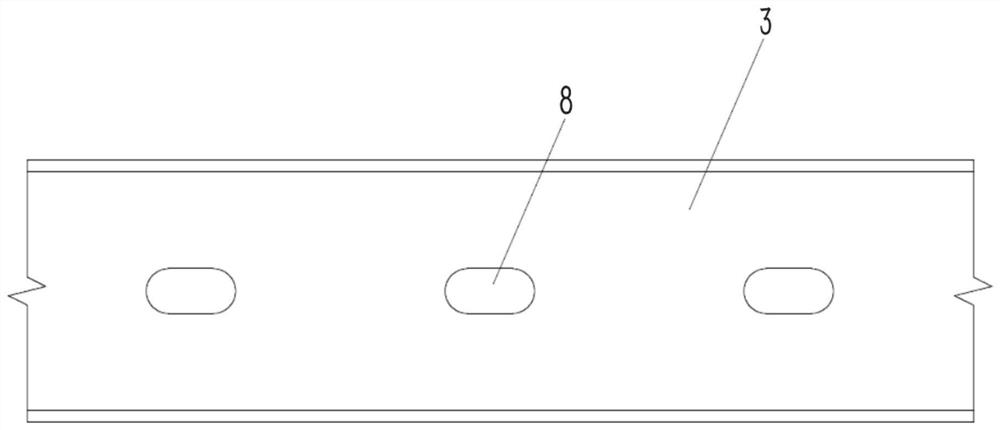
[0033] In a typical embodiment of the present disclosure, such as Figure 1-Figure 3 As shown, a composite truss node structure is given.

[0034] Aiming at the problem that the combined node position of the steel web member 4 and the concrete inner chord is easily damaged at the current node position, a composite truss node structure is provided, and the node structure of the prefabricated steel truss web-concrete composite truss structure is optimally designed to strengthen the Joint strength and stiffness, reducing the arrangement of shear keys in joint construction, and thus reducing construction costs and construction difficulties.

[0035] Specifically, the arrangement of shear keys in the node structure is reduced through the integrated node 3, the chord on the node 3 is connected to the external steel chord 2, the web on the node 3 is connected to the external steel web 4, and the integrated node 3 is buried A solid connection is formed in the concrete to meet the str...

Embodiment 2

[0061] In another embodiment of the present disclosure, as Figure 1-Figure 3 As shown, a bridge is given, which is constructed using a composite truss node as described in Example 1.

[0062] The composite truss node structure is used for the node position of the prefabricated assembled steel truss web-concrete composite truss structure, and the node 3 is embedded in the concrete slab 1 of the bridge as a whole, so as to solve the problems of concrete vertical cracking and node damage, and reduce the 4 The workload of connection processing with concrete chord nodes.

[0063] The node 3 is prefabricated in the factory, and the shear nail 7 is applied in advance, the first through hole 5 is opened as the first steel bar 6 through the hole, and the second through hole 8 is used as the concrete pouring hole; the concrete slab 1 of the bridge is used as the concrete layer of the node 3 , a plurality of nodes 3 are embedded in the concrete slab 1, and steel chords 2 arranged throu...

Embodiment 3

[0068] In yet another embodiment of the present disclosure, as Figure 1-Figure 3 As shown, a construction method of composite truss joints is given.

[0069] Include the following steps:

[0070] Install shear studs 7 on the integrated node 3 including the chord and the web, and open the first through hole 5 and the second through hole 8 on the node 3 along the direction perpendicular to the chord;

[0071] Connecting the node 3 to the external bridge structure, penetrating the first steel bar 6 in the first through hole 5, the first steel bar 6 is connected to the steel bar skeleton structure of the external bridge;

[0072] The concrete layer is coated circumferentially on the chord, so that the shear nails 7 and the first steel bar 6 are embedded in the concrete layer, and the second through hole 8 is filled in the concrete layer.

[0073] Specifically, in this embodiment, with reference to Embodiment 1, the above construction method is described in detail. Specifically...


PUM


Abstract

The invention provides a combined truss node structure, a bridge and a construction method, and relates to the technical field of bridge engineering. According to the method, aiming at the problem that a combined node position of a steel web member and a concrete inner chord member at a node position is easy to damage at present, arrangement of shear keys in a node structure is reduced through an integrated node; wherein through hole structures reserved on the joints are combined with steel bars to connect a bridge steel bar framework structure on one hand, and a pin structure is formed by concrete filled with the through holes on the other hand, so that the connection strength of the joints and a bridge concrete main body structure is improved; The structure comprises an integrated node, wherein the node comprises a chord member and a web member of which the end part is butted with the chord member; the chord member is circumferentially coated with a concrete layer, and the chord member is connected with a shear nail embedded in the concrete layer; a plurality of first through holes perpendicular to the axial direction of the chord members are formed in the positions, connected with the chord members, of the chord members and the web members, and the first through holes are matched with first steel bars penetrating through the joints and embedded in the concrete layer; the chord member is also provided with a second through hole, wherein the axis of the second through hole is vertical to the axis of the first through hole.

Description

technical field [0001] The present disclosure relates to the technical field of bridge engineering, in particular to a composite truss node structure, a bridge and a construction method. Background technique [0002] The steel-concrete composite truss structure is a new type of long-span structure. The steel truss is under tension and the concrete is under compression. These two materials play their own advantages and cooperate perfectly, which improves the shortcomings of the traditional truss structure and can be better applied in large In the construction of highway or railway bridges with a large span, it saves the amount of steel while ensuring the bearing capacity with significant advantages, and improves the spanning capacity of the truss bridge. [0003] However, due to the differences in the stress and deformation properties of concrete and steel, the mechanical properties and stress state of the combined joints of steel web members and concrete inner chords are mor...

Claims


Application Information

Patent Timeline
Patent Type & Authority Applications(China)
IPC IPC(8): E01D6/00E01D19/00E01D21/00
CPCE01D6/00E01D19/00E01D21/00
Inventor 许健宗昕彭元诚丁少凌刘潜侯淞译
Owner CCCC SECOND HIGHWAY CONSULTANTS CO LTD
Learn More