
Improved combustion furnace

A combustion furnace and an improved technology, applied in the field of combustion furnaces, can solve the problems of inability to realize thermal energy recovery and utilization, energy waste, etc., and achieve the effects of strong practicability and functionality, improved utilization rate and strong functionality.

Inactive Publication Date: 2021-11-30
杨杰川
View PDF0 Cites 0 Cited by
  • Summary
  • Abstract
  • Description
  • Claims
  • Application Information

AI Technical Summary

Problems solved by technology

However, due to the limitation of its structure, it is easy to fail to realize the function of fully recovering heat energy during the combustion process of fuel in the furnace, resulting in waste of energy

Method used


Image

  • Improved combustion furnace

Examples


Embodiment Construction

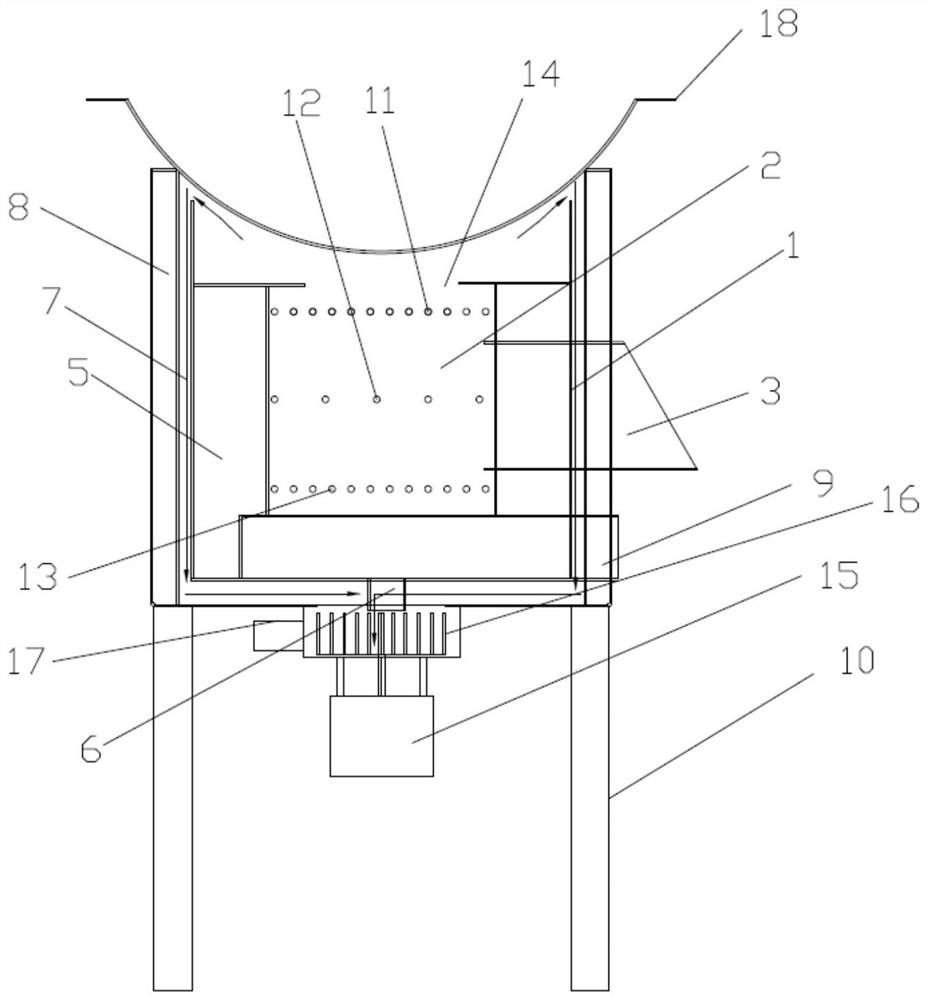
[0020] Attached below figure 1 The present invention is described in further detail.

[0021] An improved combustion furnace, comprising a furnace body 1, a furnace 2 located inside the body 1, and a slag outlet located at the lower part of the body 1, a gasification zone 5 is symmetrically arranged outside the furnace 2 and inside the body 1, and a gasification zone 5 is arranged symmetrically at the lower part of the body 1 There is a lower air inlet 6 connected with the gasification area 5, and the lower air inlet 6 is connected with an exhaust mechanism; the side of the gasification area 5 and away from the furnace 2 is provided with a return air heating area 7 connected with the furnace 2, and the return air is heated The outer side of the area 7 is provided with a thermal insulation layer 8; the lower part of the slag outlet is provided with an ash box 9, and the lower part of the main body 1 is provided with a foot 10.

[0022] The combustion furnace can use combustibl...


PUM


Abstract

The invention discloses an improved combustion furnace which comprises a furnace body, a hearth located in the furnace body, a feeding port, a side air inlet and a slag discharging port, wherein the feeding port and the side air inlet are located in the side portion of the furnace body, and the slag discharging port located in the lower portion of the furnace body. Gasification areas are symmetrically arranged outside the hearth and located in the furnace body, a lower air inlet communicated with the gasification areas is formed in the lower portion of the furnace body, and the lower air inlet is connected with an exhaust mechanism; return air heating areas communicated with the hearth are arranged at the sides, away from the hearth, of the gasification areas, and heat insulation layers are arranged at the outer sides of the return air heating areas; and an ash box is arranged on the lower portion of the slag discharging opening, and supporting legs are arranged on the lower portion of the furnace body. The improved combustion furnace is high in practicability and functionality and can be widely applied to the technical field of combustion furnaces.

Description

technical field [0001] The invention relates to the technical field of combustion furnaces, in particular to an improved combustion furnace. Background technique [0002] In the combustion furnace in the prior art, in the process of converting the chemical energy of the fuel into heat energy, the general process is: the fuel is fed into the furnace through the feed port for combustion, and then the heat energy generated by it is utilized, thereby achieving stable output function. However, due to the limitation of its structure, it is easy to fail to realize the function of fully recovering and utilizing heat energy during the combustion process of fuel in the furnace, resulting in waste of energy. [0003] Therefore, a kind of device that can overcome above-mentioned shortcoming waits to be proposed. Contents of the invention [0004] In view of the above problems, the present invention proposes a combustion furnace capable of fully recovering and utilizing the generated...

Claims


Application Information

Patent Timeline
Patent Type & Authority Applications(China)
IPC IPC(8): F23B90/06F23J1/00F23L7/00
CPCF23B90/06F23J1/00F23L7/007Y02E20/34
Inventor 杨杰川
Owner 杨杰川
Learn More