Wafer-level chip packaging technology adopting cutting channel groove process chip

A technology of wafer-level chips and dicing lanes, which is applied in the manufacture of electrical components, electrical solid-state devices, and semiconductor/solid-state devices. Achieve the effect of eliminating metal over-plating, appearance problems or electrical problems

Pending Publication Date: 2021-11-30
SHANGHAI HUAHONG GRACE SEMICON MFG CORP
View PDF0 Cites 0 Cited by
  • Summary
  • Abstract
  • Description
  • Claims
  • Application Information

AI Technical Summary

Problems solved by technology

That is to say, the metal layer is formed where the metal layer should not be formed, resulting in metal overplating in the redistribution layer, causing appearance problems in the redistribution layer, and even causing other electrical problems

Method used


Image

  • Wafer-level chip packaging technology adopting cutting channel groove process chip
  • Wafer-level chip packaging technology adopting cutting channel groove process chip
  • Wafer-level chip packaging technology adopting cutting channel groove process chip

Examples


Embodiment Construction

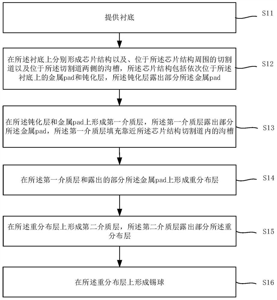
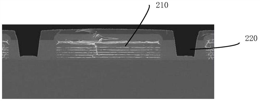
[0032] The specific implementation manner of the present invention will be described in more detail below with reference to schematic diagrams. The advantages and features of the present invention will be more apparent from the following description. It should be noted that all the drawings are in a very simplified form and use imprecise scales, and are only used to facilitate and clearly assist the purpose of illustrating the embodiments of the present invention.

[0033] Hereinafter, the terms "first", "second", etc. are used to distinguish between similar elements, and are not necessarily used to describe a specific order or chronological order. It is to be understood that these terms so used are interchangeable under appropriate circumstances. Similarly, if a method described herein includes a series of steps, the order in which these steps are presented is not necessarily the only order in which these steps can be performed, and some described steps may be omitted and / or...


PUM


Abstract

The invention provides a wafer-level chip packaging technology adopting a cutting channel groove process chip. The technology comprises the following steps that: a chip structure, a cutting channel positioned around the chip structure and grooves positioned at the two sides of the cutting channel are respectively formed on a substrate, the chip structure comprises a metal pad and a passivation layer which are sequentially positioned on the substrate, the passivation layer exposes part of the metal pad; a first dielectric layer is formed on the passivation layer and the metal pad, a part of the metal pad is exposed out of the first dielectric layer, and the groove close to the chip structure is filled with the first dielectric layer; a redistribution layer is formed on the first dielectric layer and the metal pad; a second dielectric layer is formed on the redistribution layer, wherein the second dielectric layer exposes part of the redistribution layer; and a solder ball is formed on the redistribution layer. According to the invention, the condition of excessive metal plating of the redistribution layer above or near the groove can be reduced or even eliminated, so that the condition of appearance problem or electrical problem of the redistribution layer can be reduced or even eliminated.

Description

technical field [0001] The invention relates to semiconductor packaging technology, in particular to a wafer-level chip packaging technology using a dicing line groove process chip. Background technique [0002] Wafer level chip packaging (WLCSP) is a semiconductor chip packaging process. In the wafer-level chip packaging process, the chip needs to be cut in a dicing line to divide multiple chips into single chips, and the dicing line is generally located around the chip. Since the dicing road is mainly formed by oxides (the main component of the test pad including WAT) such as silicon dioxide, the mechanical force generated during cutting is likely to vibrate the chip, which may cause chip rupture and damage to the chip in severe cases, so , a groove is made on both sides of the dicing road, so that when cutting the oxide, the groove can prevent the mechanical force generated by the cutting, thereby protecting the chip from being damaged by the mechanical force. [0003] ...

Claims


Application Information

Patent Timeline
Patent Type & Authority Applications(China)
IPC IPC(8): H01L21/60H01L21/027
CPCH01L24/03H01L21/0274H01L2224/0231
Inventor 韩国庆吴姗姗朱一鸣成剑钧曹秀亮
Owner SHANGHAI HUAHONG GRACE SEMICON MFG CORP
Why Eureka
Try Eureka