
Control circuit and resonant converter using same

A resonant converter and control circuit technology, applied in the field of resonant converters, can solve problems such as poor dynamic response, and achieve the effects of simple control, easy implementation and low cost

Pending Publication Date: 2021-11-30
SILERGY SEMICON TECH (HANGZHOU) CO LTD
View PDF0 Cites 0 Cited by
  • Summary
  • Abstract
  • Description
  • Claims
  • Application Information

AI Technical Summary

Problems solved by technology

[0003] In view of this, the embodiment of the present invention provides a control circuit and a resonant converter using it to solve the problem of poor dynamic response of existing solutions

Method used


Image

  • Control circuit and resonant converter using same
  • Control circuit and resonant converter using same
  • Control circuit and resonant converter using same

Examples


Embodiment Construction

[0031] The present invention is described below based on examples, but the present invention is not limited to these examples. In the following detailed description of the invention, some specific details are set forth in detail. The present invention can be fully understood by those skilled in the art without the description of these detailed parts. In order not to obscure the essence of the present invention, well-known methods, procedures, procedures, components and circuits have not been described in detail.

[0032] Additionally, those of ordinary skill in the art will appreciate that the drawings provided herein are for illustrative purposes and are not necessarily drawn to scale.

[0033] Meanwhile, it should be understood that in the following description, "circuit" refers to a conductive loop formed by at least one element or sub-circuit through electrical connection or electromagnetic connection. When an element or circuit is said to be "connected to" another eleme...


PUM


Abstract

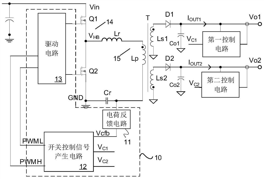
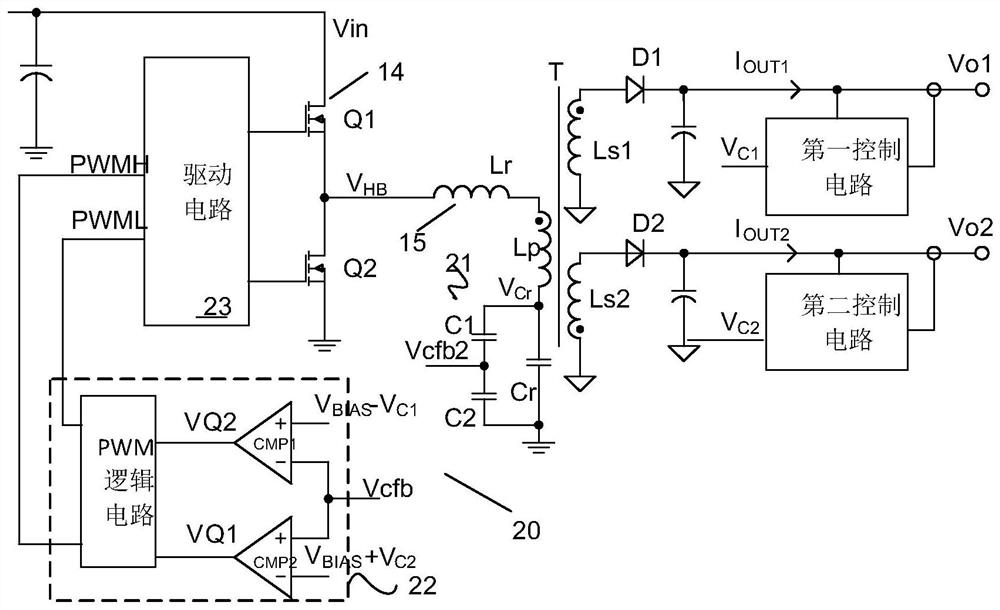
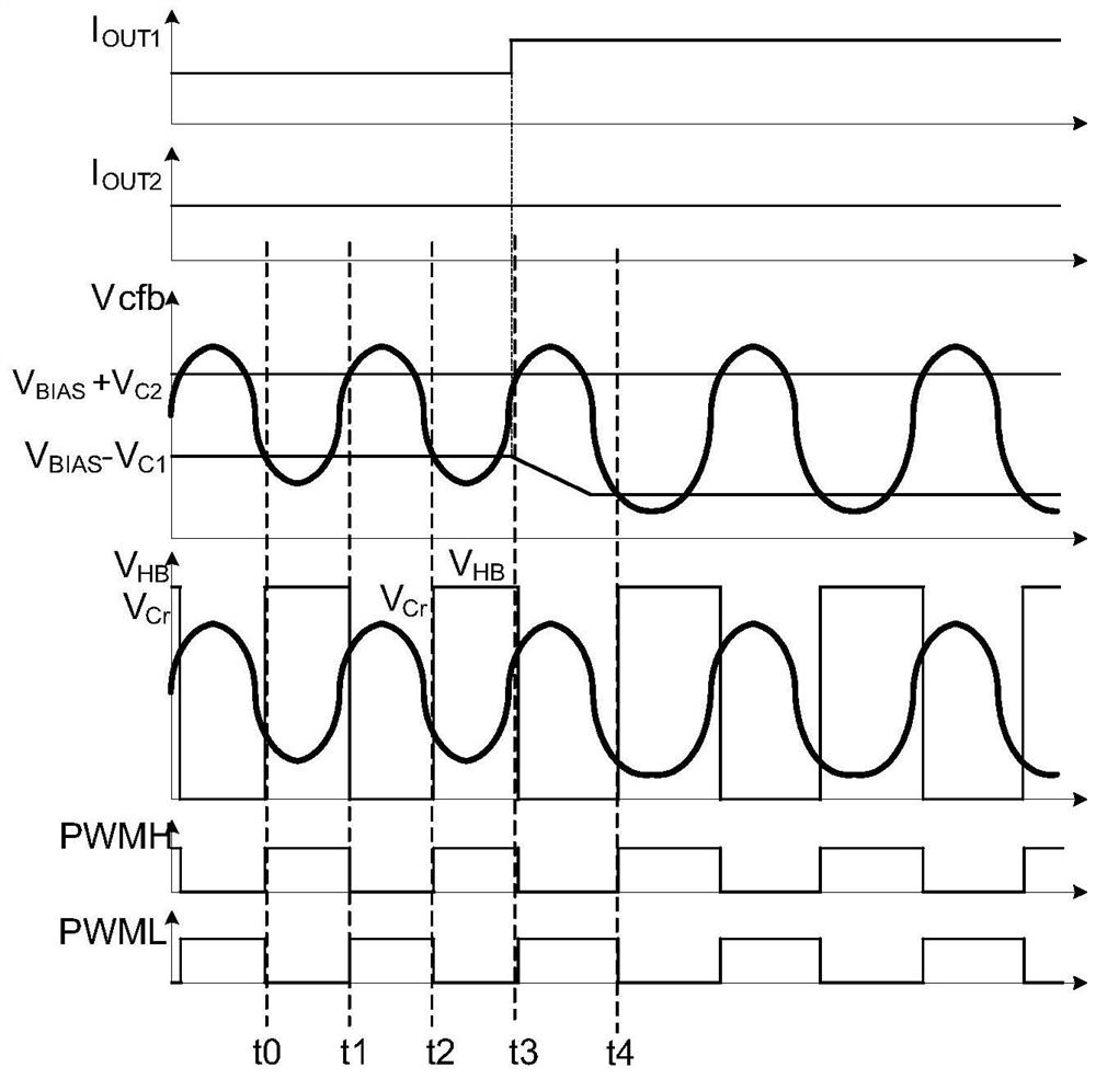
The present invention discloses a resonant converter. A resonant current is sampled to generate a charge feedback signal representing an input charge, and a switching control signal is generated according to the charge feedback signal and feedback signals output by two paths, so that the turn-on time of a transistor in a switching circuit is adjusted by changing the turn-off moment of the transistor. According to the control method, a first-stage charge inner ring is added on the basis of closed-loop control of two paths of output, but the whole control loop is simplified into an approximate first-order system, so that higher bandwidth can be controlled, the dynamic response performance is more excellent, and the control method is easier to implement due to simple control and very low cost.

Description

technical field [0001] The present invention relates to power electronics technology, in particular to power conversion technology, and more specifically, to a control circuit and a resonant converter using the same. Background technique [0002] Compared with the traditional switching converter, the resonant converter has the advantages of low switching loss, high conversion efficiency and high power density. In a conventional multi-output resonant converter, multiple output signals are adjusted by directly controlling the conduction time of the switching tubes in the half-bridge, which is equivalent to frequency control, and frequency control has poor dynamic response due to the limited bandwidth of the resonant converter. affect system performance. Contents of the invention [0003] In view of this, an embodiment of the present invention provides a control circuit and a resonant converter using the same, so as to solve the problem of poor dynamic response in the existi...

Claims


Application Information

Patent Timeline
IPC IPC(8): H02M3/335H02M7/48
CPCH02M3/33569H02M7/48Y02B70/10H02M3/01H02M3/33571H02M1/38H02M1/0009H02M3/33561
Inventor 邓建章夏荷黄秋凯
Owner SILERGY SEMICON TECH (HANGZHOU) CO LTD
Learn More